Novel energy-saving stove of gas having a flat top side
A gas stove, a brand-new technology, applied in the direction of stove/stove top, burner, combustion method, etc., can solve the problems of inconsistency in plane visual effects, lack of beautification of the kitchen, etc., to improve heating efficiency and ensure full combustion , Improve the effect of mixing uniformity
- Summary
- Abstract
- Description
- Claims
- Application Information
AI Technical Summary
Problems solved by technology
Method used
Image

Examples
no. 2 approach 200
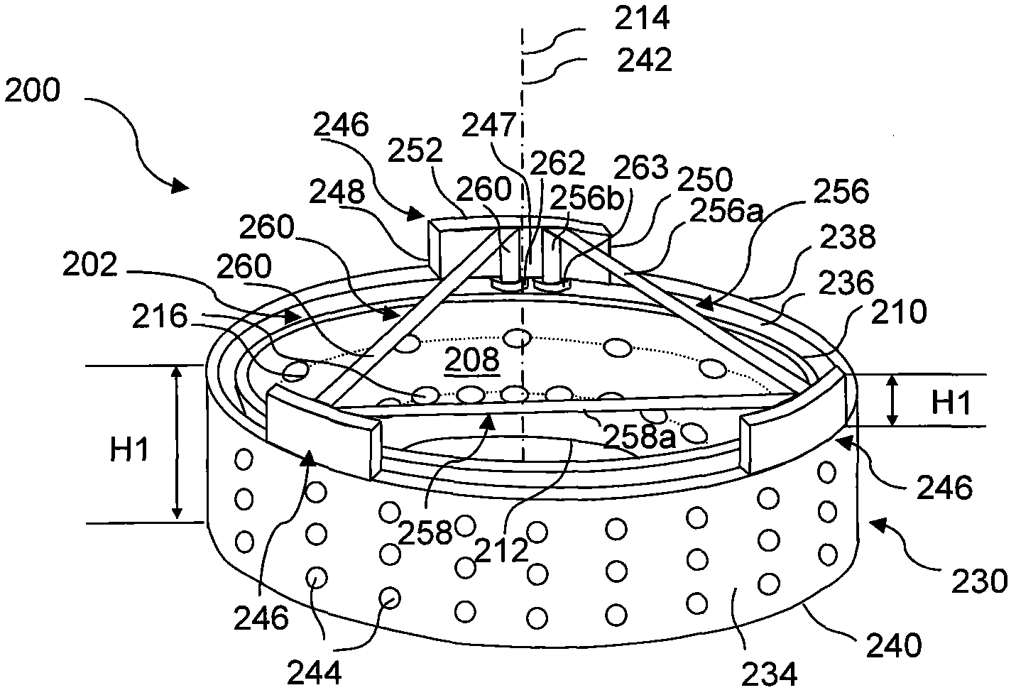
[0134] Figure 4 A second embodiment 200 of the invention is described comprising a hollow annular concave inner disk 202 and a cylindrical periphery 230 .
[0135] It can be confirmed that the inner tray 202 is exactly the same as the inner tray 102 in the first embodiment, so every structure of the inner tray 202 will not be described again. The structure of inner disk 202 is in Figure 4 is represented by a number with 3 digits. For a structure of the inner disc 202 because it is the same as the same structure in the inner disc 102 , the numbers of the first and second digits among the numbers marking the structure are the same as the numbers in the inner disc 102 . The difference is that the third digit is replaced with 200 instead of 100 in the inner disk 102 .
[0136]As shown, the cylindrical periphery 230 has a height "H12" and has an outer cylinder 234 or outer surface, an inner cylinder 236 or inner surface, a top edge 238 of a top circumferential opening, and a b...
example (I
[0147] Disclosed below are examples of the application of the device for controlling flame heat transfer of the present invention on a burner. This example is provided only to verify the above statement that the present invention can improve heating efficiency, but not to limit the present invention. However, in order to reduce space, the following disclosure only describes the results of examples. Details regarding examples can be found in US Patent Application No. 12 / 313,940.
[0148] Table 1: Results of tests on experimental and control samples
[0149] test
sample
cooking utensils
time (minutes)
time difference (minutes)
is the % of the control sample
Increased Efficiency %
1
experiment
teapot
18.75
-4.50
81.44
+18.56
2
control
teapot
24.25
[0150] 3
control
aluminum pan
24.67
4
experiment
aluminum pan
21.0...
example (II
[0174] Disclosed below are examples of the application of the present invention to a gas furnace burner. This example is provided only to verify the above statement that the present invention can improve heating efficiency, but not to limit the present invention. However, in order to reduce space, the following disclosure only describes the results of examples. Details regarding examples can be found in US Patent Application No. 12 / 313,940.
[0175] Table 2: Test results for the experimental sample (I-Cap) and the control sample (C-Cap)
[0176] test
sample
cooking utensils
time (minutes)
time difference (minutes)
% of control sample
Increase efficiency%
1
C-Cap
teapot
10.38
2
C-Cap
teapot
10.50
3
I-Cap
teapot
9.38
-1.14
89.09
10.91
[0177] The experimental results listed in Table 2 demonstrate that the use of the inner pan of the pre...
PUM
 Abstract
Description
Claims
Application Information
 - R&D
- Intellectual Property
- Life Sciences
- Materials
- Tech Scout
- Unparalleled Data Quality
- Higher Quality Content
- 60% Fewer Hallucinations
Browse by: Latest US Patents, China's latest patents, Technical Efficacy Thesaurus, Application Domain, Technology Topic, Popular Technical Reports.
© 2025 PatSnap. All rights reserved.Legal|Privacy policy|Modern Slavery Act Transparency Statement|Sitemap|About US| Contact US: help@patsnap.com