Combustion device
A technology of a combustion device and a burner, which is applied in the direction of combustion type, combustion method, lighting and heating equipment, etc., can solve the problems of increased cost, equipment cost and high maintenance cost
- Summary
- Abstract
- Description
- Claims
- Application Information
AI Technical Summary
Problems solved by technology
Method used
Image


Examples
no. 1 Embodiment
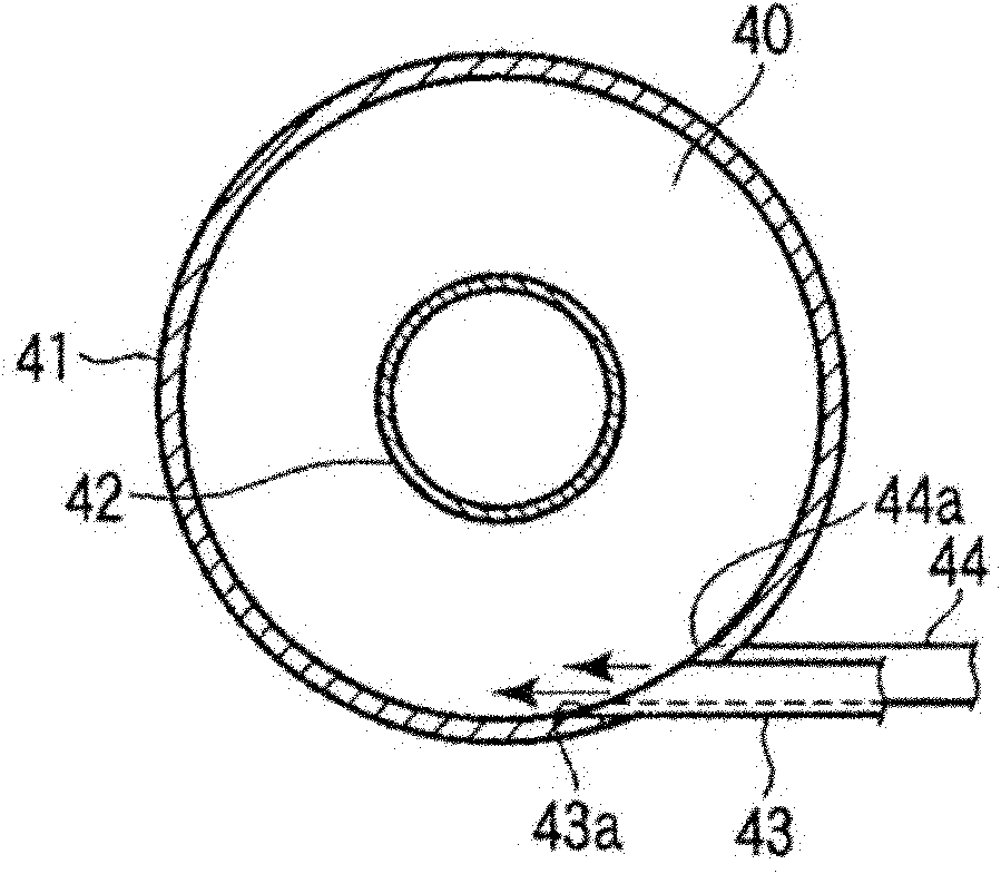
[0030] refer to figure 1 and Fig. 2 illustrate the combustion device of the first embodiment.
[0031] figure 1 The waste treatment system 1 of the illustrated embodiment includes a pyrolysis furnace 3 , a combustion device 4 , a heat utilization device 5 , and a coal dust recovery container 6 . A single or a plurality of blowers (not shown) arranged on the downstream side in the processing system 1 suck exhaust gas. In addition, the whole processing system 1 is managed and controlled comprehensively by the process control computer which is not shown in figure. The pyrolysis furnace 3 pyrolyzes organic wastes in a high-temperature reducing gas environment. The combustion device 4 burns combustible pyrolysis gas generated in the pyrolysis furnace 3 . The heating device 5 utilizes the high-temperature combustion exhaust gas discharged from the combustion device 4 . Hereinafter, each constituent unit of the waste treatment system 1 will be described.
[0032]The pyrolysis f...
no. 2 Embodiment
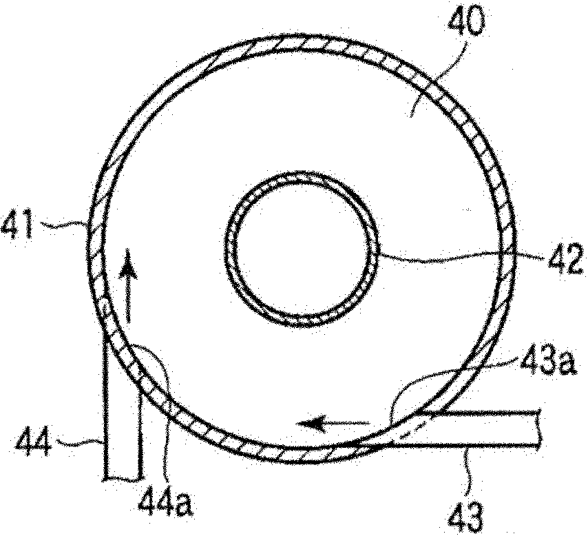
[0044] Next, refer to image 3 The second embodiment will be described. In addition, the description of the parts common to the first embodiment will be omitted.
[0045] Combustion device 4A of present embodiment does not possess in the bottom of device figure 1 Shown coal dust recovery container 6. The combustion device 4A includes a bottom cover 49 that closes the lower end opening of the outer cylinder 41 . The bottom cover 49 can be opened and closed.
[0046] In the combustion device of this embodiment, the coal dust 60 adheres to the inner peripheral wall of the outer cylinder 41 , and finally peels off from the wall surface and accumulates on the bottom cover 49 . The bottom cover 49 is opened regularly, and the accumulated coal dust 60 is recovered from the outer cylinder 41 .
[0047] According to this embodiment, the outer cylinder 41 with the bottom cover 49 functions as a dust collection container. Therefore, since 4 A of combustion apparatuses do not need a...
no. 3 Embodiment
[0049] Next, refer to Figure 4 The third embodiment will be described. In addition, descriptions of parts common to the above-described embodiments are omitted.
[0050] In the combustion device 4B of this embodiment, the shape of the lower half of the outer cylinder is an inverted conical cylinder shape. That is, the shape of the upper half part 41a of an outer cylinder is cylindrical. The shape of the lower half part 41b of the outer cylinder is an inverted cone shape, and the lowermost part 41c of the outer cylinder is a small cylindrical shape. The lowermost part 41c is a discharge part. The inner diameter of the lower half 41b of the inverted conical outer cylinder gradually decreases as it goes downward. The lower end opening 42a of the inner cylinder is located in the lower half 41b of the inverted conical outer cylinder. In addition, the lowermost portion 41c of the outer cylinder, that is, the discharge portion has an opening 41d at the lower end. The opening 4...
PUM
 Abstract
Description
Claims
Application Information
 - R&D
- Intellectual Property
- Life Sciences
- Materials
- Tech Scout
- Unparalleled Data Quality
- Higher Quality Content
- 60% Fewer Hallucinations
Browse by: Latest US Patents, China's latest patents, Technical Efficacy Thesaurus, Application Domain, Technology Topic, Popular Technical Reports.
© 2025 PatSnap. All rights reserved.Legal|Privacy policy|Modern Slavery Act Transparency Statement|Sitemap|About US| Contact US: help@patsnap.com