Multistage recirculation reactor for anaerobic sludge
A circulating reactor and anaerobic sludge technology, applied in the direction of anaerobic digestion treatment, etc., can solve the problems of sludge ineffective mixing, sludge loss, etc., to ensure high-load operation efficiency, high-efficiency response, and increase contact area Effect
- Summary
- Abstract
- Description
- Claims
- Application Information
AI Technical Summary
Problems solved by technology
Method used
Image
Examples
Embodiment 1
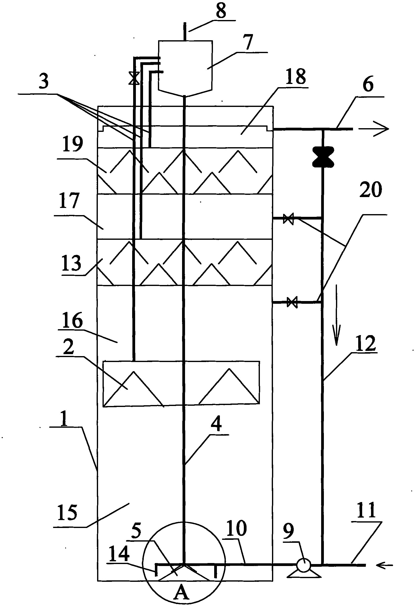
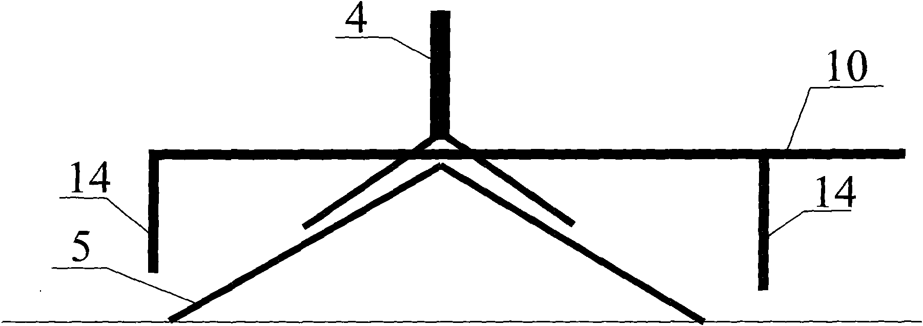
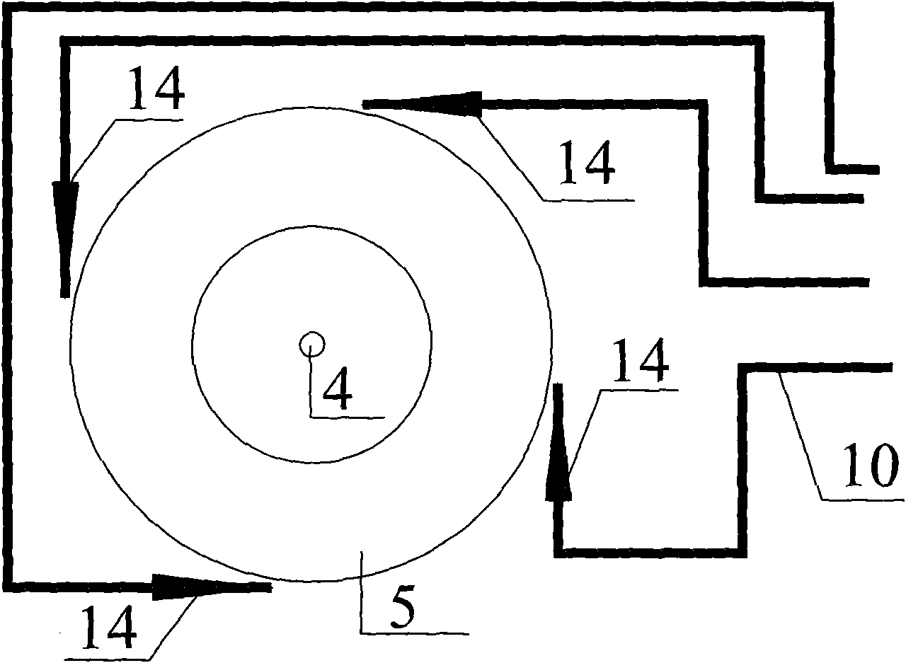
[0025] An anaerobic sludge multi-stage circulation reactor, including reactor 1, water inlet pipe I11, water inlet pipe II10, water outlet pipe 6 and gas-liquid separation tank 7, water inlet pipe I11 is located at the lower end of reactor 1, and water inlet pipe II10 passes through the reaction The water pump 9 outside the reactor 1 is connected to the water inlet pipe I11, the outlet pipe 6 is set at the upper end of the reactor 1, the gas-liquid separation tank 7 is set at the top of the reactor 1, the cross section of the reactor 1 is circular, and the inside of the reactor 1 passes through The upper layer three-phase separator 19, the middle layer three-phase separator 13 and the lower layer gas collector 2 arranged in sequence from top to bottom divide the whole reactor into a precipitation zone 18, an upper layer reaction zone 17, a middle layer reaction zone 16 and a lower layer reaction zone 15 The lower gas collector 2 is a single-layer gas collecting hood; the bottom...
Embodiment 2
[0032] An anaerobic sludge multi-stage circulation reactor, comprising a reactor, a water inlet pipe I, a water inlet pipe II, an outlet pipe 6 and a gas-liquid separation tank, the water inlet pipe I is arranged at the lower end outside the reactor, and the water inlet pipe II passes through the The water pump is connected to the water inlet pipe I, the water outlet pipe is set at the upper end of the reactor, and the gas-liquid separation tank is set at the top of the reactor. The whole reactor is divided into a precipitation zone, an upper layer reaction zone, a middle layer reaction zone and a lower layer reaction zone; the lower layer gas collector is a single-layer gas collection hood; the bottom of the gas-liquid separation tank is connected There is an internal reflux circulation pipe extending to the inner bottom of the reactor; the inner bottom of the reactor is provided with an internal reflux liquid deflector corresponding to the outlet of the internal reflux circul...
Embodiment 3
[0035] An anaerobic sludge multi-stage circulation reactor, including a reactor, a water inlet pipe I, a water inlet pipe II, an outlet pipe and a gas-liquid separation tank, the water inlet pipe I is arranged at the lower end outside the reactor, and the water inlet pipe II passes through a water pump outside the reactor It is connected with the water inlet pipe I, the water outlet pipe is set at the upper end of the reactor, and the gas-liquid separation tank is set at the top of the reactor. , the middle three-phase separator and the lower gas collector divide the whole reactor into a precipitation zone, an upper reaction zone, a middle reaction zone and a lower reaction zone; the lower gas collector is a single-layer gas collecting hood; the bottom of the gas-liquid separation tank is connected with The internal reflux circulation pipe extending to the inner bottom of the reactor; the inner bottom of the reactor is provided with an internal reflux liquid deflector correspon...
PUM
 Abstract
Description
Claims
Application Information
 - R&D
- Intellectual Property
- Life Sciences
- Materials
- Tech Scout
- Unparalleled Data Quality
- Higher Quality Content
- 60% Fewer Hallucinations
Browse by: Latest US Patents, China's latest patents, Technical Efficacy Thesaurus, Application Domain, Technology Topic, Popular Technical Reports.
© 2025 PatSnap. All rights reserved.Legal|Privacy policy|Modern Slavery Act Transparency Statement|Sitemap|About US| Contact US: help@patsnap.com


