
Method and system for controlling microstrip antenna energy distribution

An energy distribution, microstrip antenna technology, applied to antennas, electrical components, etc., to shorten the difference between wake-up and transaction distance, ensure transaction success rate, and suppress interference.

Active Publication Date: 2013-10-09
CHINA TRANSINFO TECH CORP
View PDF0 Cites 0 Cited by
  • Summary
  • Abstract
  • Description
  • Claims
  • Application Information

AI Technical Summary

Problems solved by technology

[0006] The present invention provides a microstrip antenna energy distribution control method and control system to solve the problem that the wake-up and transaction distances of different OBUs vary greatly due to the design of the existing RSU antenna The problem

Method used


Image

  • Method and system for controlling microstrip antenna energy distribution
  • Method and system for controlling microstrip antenna energy distribution
  • Method and system for controlling microstrip antenna energy distribution

Examples


Embodiment Construction

[0040] In order to make the above objects, features and advantages of the present invention more comprehensible, the present invention will be further described in detail below in conjunction with the accompanying drawings and specific embodiments.

[0041] Based on the beamforming technology, the present invention proposes a microstrip antenna energy distribution control method, which is completely different from the prior art design method based on the 3dB angle range in the ETC national standard, and can be reverse-designed based on the actual required power distribution, A microstrip antenna capable of radiating such a power distribution is thus determined. Wherein, the beamforming refers to changing the shape of the antenna beam pattern into a specified beam shape by adjusting the excitation of each array element of the array antenna.

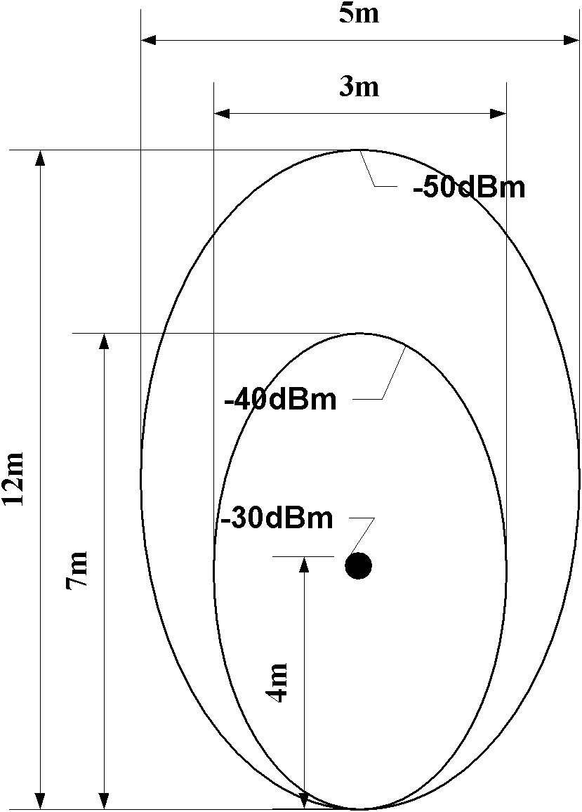
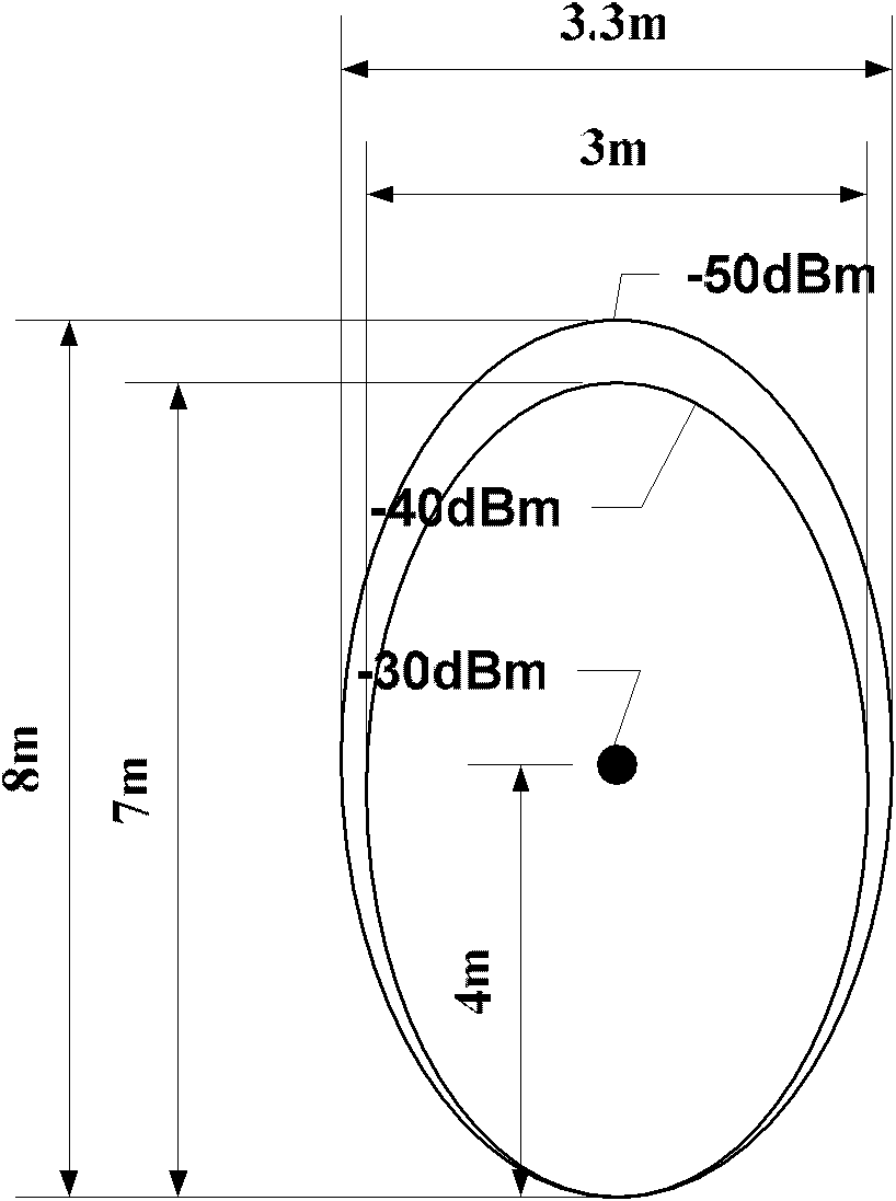
[0042] For example, in the prior art microstrip antenna design, when -40dBm to -50dBm

[0043] For the above figure 1 with figure 2 ...


PUM


Abstract

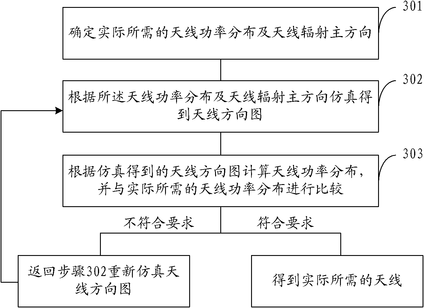
The invention provides a method and system for controlling microstrip antenna energy distribution, which solve the problem that the waking and transacting distance differences of different on-board units (OBUs) are large caused by the design of a remote subscriber unit (RSU) antenna. The method comprises the following steps: determining the actually needed antenna power distribution and the antenna radiation main direction; stimulating according to the antenna radiator power distribution and the antenna radiation main direction to obtain an antenna directional pattern; calculating the antenna power distribution according to the antenna directional pattern obtained by simulation; and comparing with the actually needed antenna power distribution, if the preset requirement is met, obtaining the actually needed antenna, and if the preset requirement is not met, simulating the antenna directional pattern again until the preset requirement is met. By the method and system provided by the invention, the distribution of the radiation energy of the designed antenna is controlled in an actually needed fixed range, and the waking and transacting distance differences of the OBUs with different sensitivities are shortened, thus satisfying the communication demands of the RSU and the OBU, and the temporary interference of vehicles can be inhibited.

Description

technical field [0001] The invention relates to microwave communication technology, in particular to a microstrip antenna energy distribution control method and control system. Background technique [0002] The microstrip antenna is a microwave antenna composed of depositing or attaching metal strips and sheets of required shape on a dielectric substrate with a metal ground plate. Microstrip antennas have the advantages of miniaturization, easy integration, and good directivity, so their application prospects are broad. For example, the microstrip antenna is applied to an ETC (Electronic Toll Collection, Electronic Toll Collection) system. [0003] The ETC system mainly includes roadside units and vehicle-mounted units. Road-Side Units (RSU for short) consist of a microstrip antenna and a read-write controller. The microstrip antenna is a microwave transceiver module for signal and data reception / transmission, modulation / demodulation, and encoding / decoding, encryption / d...

Claims


Application Information

Patent Timeline
Patent Type & Authority Patents(China)
IPC IPC(8): H01Q3/26
Inventor 汪飞赵志泳周双全张志平夏曙东
Owner CHINA TRANSINFO TECH CORP
Learn More