Spray valve control system of spray tower

A control system, spray tower technology, applied in valve details, valve device, valve operation/release device, etc., can solve the problem of unable to change the ratio of water pressure to air pressure, spray tower bottom corrosion, spray tower wall corrosion and other problems, to achieve the best atomization effect, avoid long-term electrification, and avoid excessive corrosion.

Active Publication Date: 2011-07-27
SNTO TECH GRP
View PDF3 Cites 3 Cited by
  • Summary
  • Abstract
  • Description
  • Claims
  • Application Information

AI Technical Summary

Problems solved by technology

The existing control technology has the following disadvantages: 1. The roasting temperature is generally 140 to 160 degrees. The first group of valves takes the most time to open, while the other two groups of valves basically do not open. The spraying is disabled for a long time, and it is easy to block after corrosion. Nozzle; 2. The roasting flue gas contains sulfur. After atomization, it will form a weak acid with the flue gas, and the pH value is less than 4. This kind of acid mist is easy to cause corrosion of the spray tower wall, and the first group of valves has the longest opening time. , the acid mist generated on this side is the most, and the tower wall near the first group of spray solenoid valves is extremely corroded. The actual situation is that after the first group of solenoid valves has been perforated, the opposite tower wall is still 10mm thick, basically uncorroded; 3. The ratio of water pressure and air pressure cannot be changed in the existing control instructions, and the best effect of atomization cannot be achieved. After excessive water spraying, acidic liquid will be formed at the bottom of the spray tower, which will cause great corrosion to the bottom of the spray tower. If it is not enough, it will not be able to cool the flue gas; 4. Based on the emergency consideration of power failure, the original design of the solenoid valve is a normally open valve.

Method used


Image

  • Spray valve control system of spray tower
  • Spray valve control system of spray tower
  • Spray valve control system of spray tower

Examples


Embodiment 1

[0045] A spray valve control system for a spray tower, including a water spray solenoid valve, an air spray solenoid valve, a booster pump, a pressure gauge, a flow meter, an automatic regulating valve and a PLC controller, and the PLC controller controls two groups of solenoid valves 11 , 12 controls water spray and air spray, and a cycle control module is designed in the PLC controller to realize two sets of solenoid valves 11 and 12 to be controlled in sequence: when the spray tower starts to work, the solenoid valve 11 is the first group of solenoid valves, and the solenoid valve 12 It is the second group of solenoid valves; after four hours of the preset time, the PLC controller sends an adjustment command, the solenoid valve 12 is the first group of solenoid valves, and the solenoid valve 11 is the second group of solenoid valves; after eight hours of the preset time, Each group of solenoid valves returns to the original state, that is, the solenoid valve 11 is the first ...

Embodiment 2

[0049] A spray valve control system for a spray tower, including a water spray solenoid valve, an air spray solenoid valve, a booster pump, a pressure gauge, a flow meter, an automatic regulating valve and a PLC controller, and the PLC controller controls two groups of solenoid valves 11 , 12 controls water spray and air spray, and a cycle control module is designed in the PLC controller to realize two sets of solenoid valves 11 and 12 to be controlled in sequence: when the spray tower starts to work, the solenoid valve 11 is the first group of solenoid valves, and the solenoid valve 12 It is the second group of solenoid valves; after six hours of the preset time, the PLC controller sends an adjustment command, the solenoid valve 12 is the first group of solenoid valves, and the solenoid valve 11 is the second group of solenoid valves; after twelve hours of the preset time , each group of solenoid valves returns to the original state, that is, the solenoid valve 11 is the first...

Embodiment 3

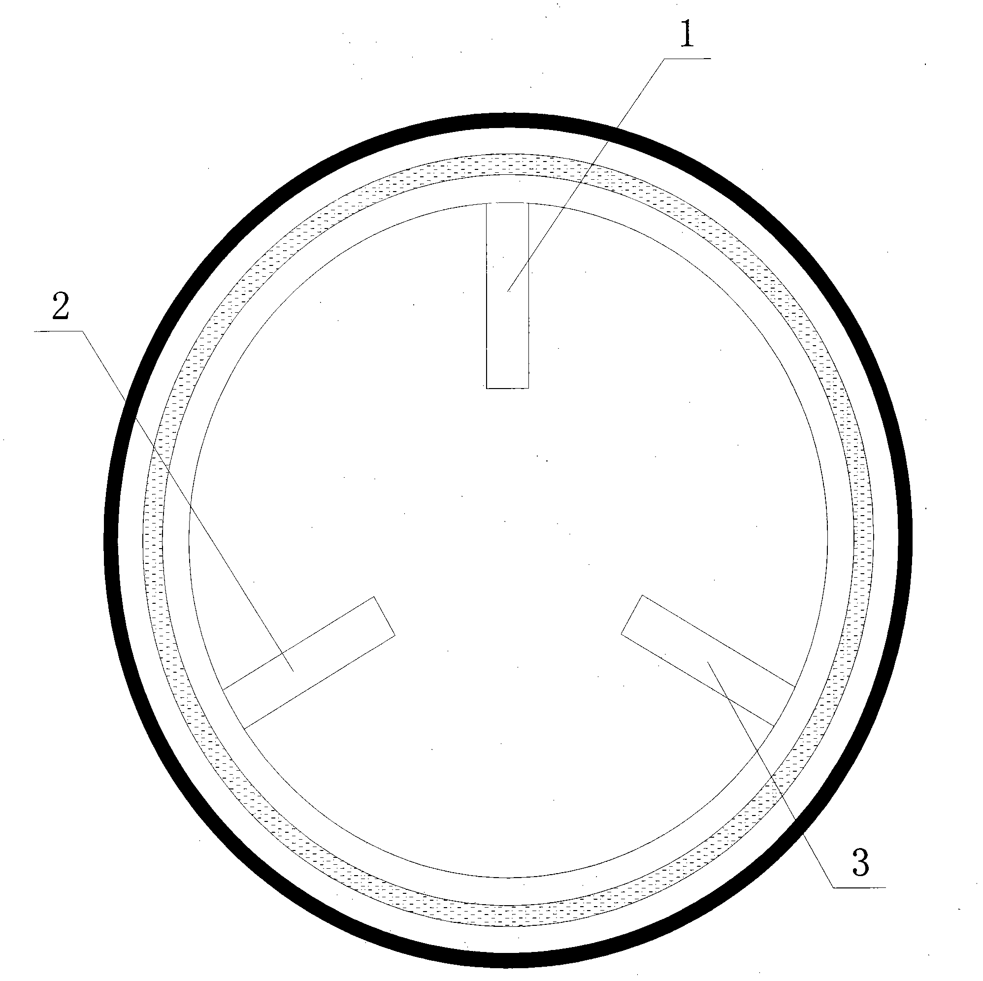
[0053] Such as figure 1 As shown, a spray valve control system of a spray tower, the spray tower includes three sets of solenoid valves 11, 12, 13 controlled by a PLC controller, and three sets of solenoid valves 11, 12, 13 control the water spray valve and air spray For the opening and closing of the valve, a cycle control module is designed in the PLC controller to realize the sequential control of three sets of solenoid valves 11, 12, and 13: when the spray tower starts to work, the solenoid valve 11 is the first set of solenoid valves, and the solenoid valve 12 is the second group of solenoid valves, and solenoid valve 13 is the third group of solenoid valves; after four hours, the PLC controller sends an adjustment command, solenoid valve 12 is the first group of solenoid valves, solenoid valve 13 is the second group of solenoid valves, and the solenoid valve 13 is the second group of solenoid valves. Valve 11 is the third group of solenoid valves; after eight hours, the ...


PUM

PropertyMeasurementUnit
thicknessaaaaaaaaaa

Abstract

The invention relates to a spray valve control system of a spray tower. The spray valve control system of the spray tower comprises a water spraying electromagnetic valve, a gas spraying electromagnetic valve, a booster pump, a pressure gauge, a flow meter, an automatic regulating valve and a programmable logic controller (PLC), wherein at least two groups of electromagnetic valves (11, 12) whichare controlled by the PLC control water spraying and gas spraying; and a circulation control module is designed in the PLC to make each group of electromagnetic valves (11, 12) serve as the first group of valves sequentially to control the operation of spray valves. The system can send out an instruction automatically according to a preset time value to indicate that the electromagnetic valves control each spray valve to operate alternately for spraying and cooling, so that over-corrosion of the spray valve on a side and the wall of the spray tower is avoided; moreover, the PLC can change theratio of a water pressure to a gas pressure automatically, so that an atomization effect is better.

Description

1. Technical field [0001] The invention belongs to the field of automatic control desulfurization and dust-proof equipment, and in particular relates to a spray valve control system of a spray tower. 2. Background technology [0002] The existing spray and atomization device includes water spray solenoid valve, air spray solenoid valve, booster pump, pressure gauge, flow meter, and automatic regulating valve. When the temperature of the flue gas exceeds the set value, the PLC controller will issue an opening after receiving the instruction. The information of the first group of water spray valves and air spray valves, the solenoid valves are turned on to start spraying, to achieve cooling effect, the six solenoid valves are divided into three groups, distributed in an equilateral triangle, when the flue gas temperature reaches 130 degrees, open One group of solenoid valves, when the temperature reaches 150 degrees, open the second group of solenoid valves, and when the tempe...

Claims


Application Information

Patent Timeline
Patent Type & Authority Applications(China)
IPC IPC(8): B01D53/78B01D53/48B01D47/06F16K31/00
Inventor 张友权
Owner SNTO TECH GRP
Why Eureka
Try Eureka