Conductor with U-shaped welded junction

A technology for welding joints and conductors, which is applied in the direction of welding/welding connection, clamping/spring connection, multi-core cable end parts, etc., which can solve the problems of weak welding, small contact area, and easy falling off.

Inactive Publication Date: 2011-07-20
SUZHOU HARDI ENERGY TECH CO LTD
View PDF6 Cites 3 Cited by
  • Summary
  • Abstract
  • Description
  • Claims
  • Application Information

AI Technical Summary

Problems solved by technology

The conductive body with this tubular socket interface has only an annular surface at the interface at the welding point with the wire

Method used


Image

  • Conductor with U-shaped welded junction
  • Conductor with U-shaped welded junction
  • Conductor with U-shaped welded junction

Examples


Embodiment Construction

[0014] The present invention will now be described in further detail in conjunction with the accompanying drawings and preferred embodiments. These drawings are all simplified schematic diagrams, which only illustrate the basic structure of the present invention in a schematic manner, so they only show the configurations related to the present invention.

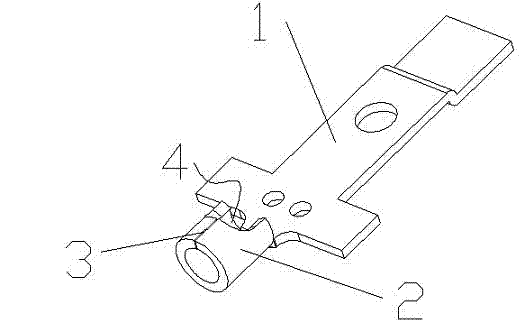
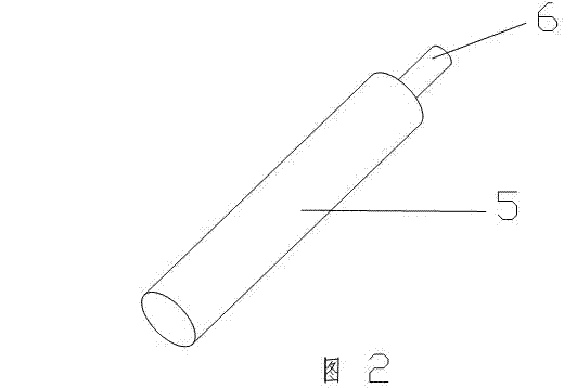
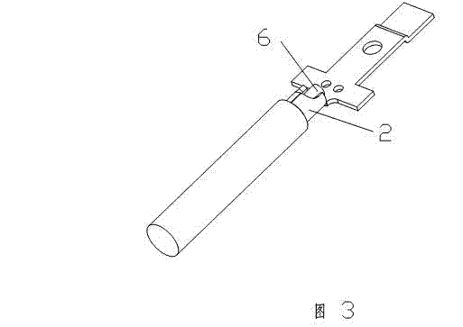
[0015] Please refer to figure 1 , the present invention discloses a conductor with a U-shaped welding port. Specifically, the body 1 of the conductor is cross-shaped, and is molded at one time using conductive materials. The bottom of the body 1 is provided with a tubular cable conductor clamping part 2, which is tubular The clamping part 2 can be combined with the inserted cable conductor 6 (please combine figure 2 ) are closely matched to clamp the cable conductor 6, and then the conductor and the cable are fixedly connected by welding.

[0016] Preferably, the upper half of the clamping part 2 is longitudinally provide...


PUM


Abstract

The invention relates to a conductor with a U-shaped welded junction, which comprises a conductive body, wherein the bottom of the conductive body is provided with a tubular clamping part; the tubular clamping part can be in close fit with an inserted cable conductor, and is provided with a through groove; and at least one end of the clamping part is provided with a U-shaped nick. In the conductor disclosed by the invention, a welding surface formed when the welded junction is in close fit with the inserted cable conductor is larger, so that the conductor is welded firmly and not easy to fall off; moreover, the structure is simple and the manufacture cost is low.

Description

technical field [0001] The invention relates to a welding joint structure of a conductor, in particular to a conductor with a U-shaped welding joint. Background technique [0002] The junction box is used for the transition of the wire / cable joint (for example, the line is relatively long, or the wire / cable pipe needs to be cornered). The wire / cable is connected in the junction box to protect the wire / cable and connect the wire. In the existing junction box, a cross-shaped conductor is generally used to weld and connect the wires / cables. Specifically, one end of the cross-shaped conductor is provided with a wire socket, and the wire socket is tubular. When in use, wires or cables are inserted into the socket, and then the wires or cables are fixed to the conductor by welding. The conductive body using this tubular socket interface only has a welding point with the wire or cable on an annular surface at the interface, and the contact area between the wire / cable and the condu...

Claims


Application Information

Patent Timeline
IPC IPC(8): H01R4/02H01R4/28H01R11/11
Inventor 詹功瀚李宝明
Owner SUZHOU HARDI ENERGY TECH CO LTD
Why Eureka
Try Eureka