Oil pressure sealing type chain tightener

A sealed and tensioner technology, applied in the direction of belts/chains/gears, mechanical equipment, transmissions, etc., can solve the problems of small output, unusable, easy chain deviation, etc., to reduce sliding resistance and smooth adjustment , Good oil pressure damping effect

Inactive Publication Date: 2011-07-20
NTN CORP
View PDF3 Cites 3 Cited by
  • Summary
  • Abstract
  • Description
  • Claims
  • Application Information

AI Technical Summary

Problems solved by technology

[0005] However, the chain tensioner described in the above-mentioned Patent Document 1 is an oil supply method for supplying oil to the oil supply passage, so it is necessary to provide an oil supply passage for guiding the oil discharged from the oil pump to the oil supply passage, resulting in an increase in the cost of the engine. Big
[0006] In addition, as the oil pump, a large oil pump with a large discharge capacity is required. The oil pump discharges a small amount when the engine is started, and it takes time until the pressure chamber of the chain tensioner is filled with oil to perform the oil pressure damping function. Rear chain prone to misalignment
[0007] Here, as described in Japanese Patent Laid-Open No. 2006-90440 or Japanese Patent Laid-Open No. 2007-24200, there is a chain tensioner of a hydraulic seal type among chain tensioners, and the hydraulic seal type described in these gazettes Type chain tensioner, since the end opening of the casing is sealed by assembling sealing components such as oil seals to prevent the oil sealed inside the casing from leaking to the outside, therefore, the above sealing components can only be used in the state of facing upward or laterally, requiring In the case of an engine that applies a downward adjustment force to the chain, there is a problem that the oil pressure damping effect cannot be exerted due to air intrusion into the pressure chamber formed inside the casing, and it cannot be used.

Method used


Image

  • Oil pressure sealing type chain tightener
  • Oil pressure sealing type chain tightener
  • Oil pressure sealing type chain tightener

Examples


Embodiment Construction

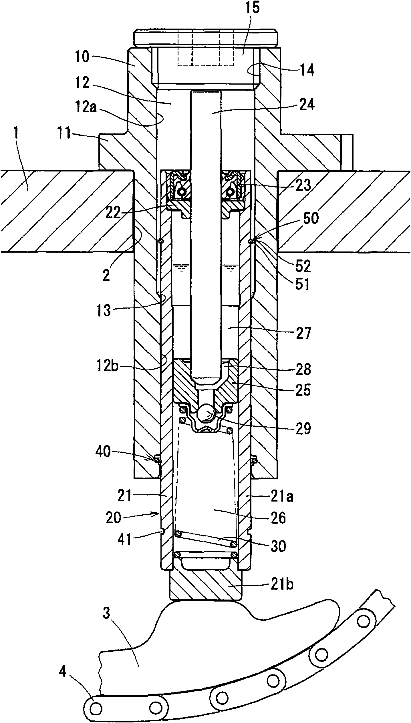
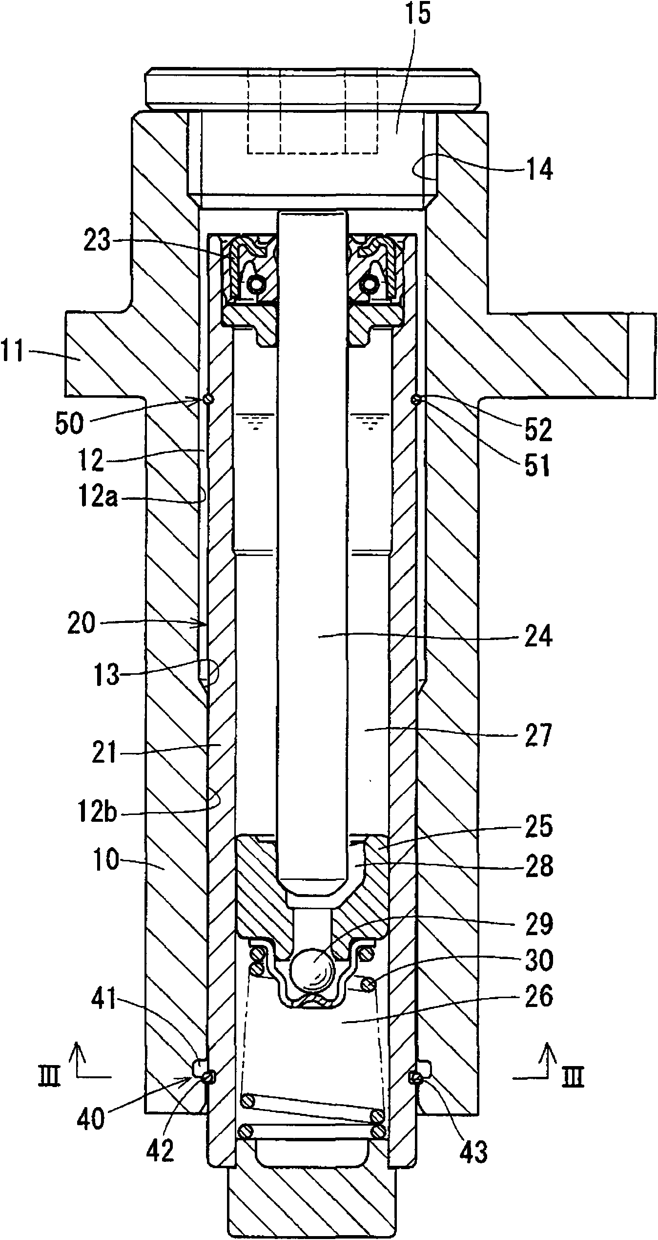
[0034] Embodiments of the present invention will be described below with reference to the drawings. Such as figure 1 As shown, the hydraulically sealed chain tensioner of the present invention is composed of a housing 10 mounted on a chain cover 1 of an engine, and a hydraulically sealed tensioner unit 20 slidably supported on the housing 10 .

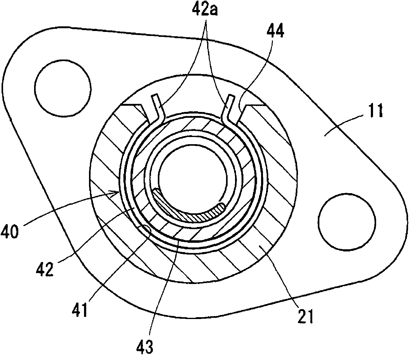
[0035] The housing 10 has a cylindrical shape and can be inserted from the outside into the tensioner mounting hole 2 formed on the upper portion of the outer peripheral wall of the chain cover 1, and a flange 11 is provided on the outer circumference of the rear end portion in the insertion direction. 11 abuts against the outer surface of the chain cover 1 and is fixed by bolts.

[0036] In addition, a guide hole 12 is formed in the housing 10 , and the guide hole 12 penetrates vertically in the mounted state to the chain cover 1 . The guide hole 12 is a stepped hole in which the small-diameter hole portion 12b is formed below the lar...


PUM


Abstract

The present invention provides an oil pressure sealing type chain tightener which can exert a downward adjusting force to the chain. An oil pressure sealing type tightening unit (20) is slidably mounted in a guiding hole (12) which is provided on a housing (10) of a chain cover (1). The oil pressure sealing type tightening unit (20) keeps a tension of the chain (4) to a constant value through the extension and contraction of a rod (24). The rod (24) slidably passes through a cylinder (21) and a sealing component (23). An upper opening of the cylinder (21) is sealed through mounting the sealing component (23). An upper end of the rod (24) of the tightening unit (20) is propped by a lower surface of a head cover (15) that closes the guiding hole (12). Furthermore a chain guiding part (3) is slidably pressed by the bottom of a cylinder (21) that is supported by the housing (10) for keeping the tension of the chain (4) constant.

Description

technical field [0001] The present invention relates to a hydraulic seal type chain tensioner which maintains a constant tension of a camshaft driving chain. Background technique [0002] In a chain transmission that transmits the rotation of the crankshaft to the camshaft via a chain, the slack side of the chain contacts a swingable chain guide, and the tension of the chain is kept constant by applying the adjustment force of the chain tensioner to the chain guide. . [0003] As the above-mentioned chain tensioner, what is described in Patent Document 1 is known. In this chain tensioner, a plunger and a return spring are assembled in a cylinder chamber formed in a casing, and the return spring presses the plunger outward; The oil supply passage, and a check valve is provided at the oil outlet of the oil supply passage. The check valve prevents the oil from flowing back to the oil supply passage side, and buffers the oil applied from the chain by the oil supplied from the ...

Claims


Application Information

Patent Timeline
Patent Type & Authority Applications(China)
IPC IPC(8): F16H7/08
Inventor 井筒智善
Owner NTN CORP
Why Eureka
Try Eureka