
Structure design method of free curved surface lens for outdoor LED (light-emitting diode) illumination

A technology of LED lighting and curved lens, applied in lighting and heating equipment, components of lighting devices, lighting devices, etc., can solve problems such as glare effect, low uniformity of illumination, and reduced brightness

Active Publication Date: 2011-07-13
BEIHANG UNIV
View PDF2 Cites 19 Cited by
  • Summary
  • Abstract
  • Description
  • Claims
  • Application Information

AI Technical Summary

Problems solved by technology

However, because the light emitted by the LED light source has a Lambertian distribution (Lambertian distribution), that is, when the light source is at a certain height from the road and perpendicular to the road, it can only form a small circular spot on the road, and the brightness is from the center of the circle to the outside. The sharp reduction and low uniformity of illumination, so LED street lamps without light distribution design, the road surface projection effect is a large area of ​​circular light spots, causing about 50% of the light to scatter beyond the required range, and the light energy utilization rate is low
In addition, there will be a glare effect, which will affect road safety and do not meet the requirements of road lighting

Method used


Image

  • Structure design method of free curved surface lens for outdoor LED (light-emitting diode) illumination
  • Structure design method of free curved surface lens for outdoor LED (light-emitting diode) illumination
  • Structure design method of free curved surface lens for outdoor LED (light-emitting diode) illumination

Examples


Embodiment 1

[0083] Suppose the length of the road is 40m, the height of the street lamp is 10m, and the width of the road is 10m. The street lamp is facing the center of the rectangular road surface. The refractive index of the lamp is taken as n=1.5, and the corresponding free-form surface is designed:

[0084] In MATLAB for:

[0085] 1 ρ ( θ ) · dρ ( θ ) = sin θ · g ( θ ) + cos θ cos θ · g ( θ ) - sin θ · dθ - - - ...

Embodiment 2

[0091] The road surface is 38m long and 11m wide. The street lamps protrude from the road surface by 1m at an inclination angle of 15°. The refractive index of the material is n=1.5. The schematic diagram of engineering requirements is as follows ( Figure 5 ):

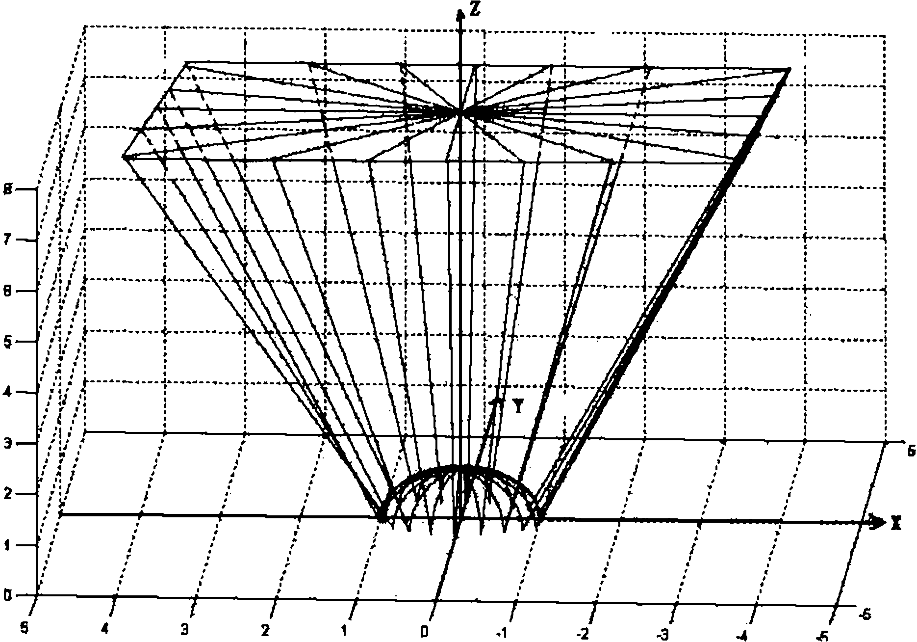
[0092] The profile of the quadratic light distribution surface is given as Image 6 :

[0093] The outer curve b is the direction along the length of the road surface In the profile, the profile curve of the secondary light distribution surface of the lamp;

[0094] The inner curve a is along the road width direction In the profile, the profile curve of the secondary light distribution surface of the lamp.


PUM


Abstract

The invention relates to a structure design method of a free curved surface lens for outdoor LED (light-emitting diode) illumination, comprising three main steps: 1, analysis of an LED light source; 2, establishment of a light-emitting model; and 3, analysis of a mathematical model, wherein firstly, the LED light-emitting model is established by computer simulation and analysis of the energy distribution characteristic; then the corresponding relationship between the original transmission ray emitted by the light source and the modulated ray is determined to establish the mathematical model by taking the shape and the size of specific transmission light spots and the installation and distribution characteristics of the LED lamp as variants; finally, by combining with the actual engineering requirements, a dependent equation set is solved by adopting mathematical simulation software to obtain surface type space distribution point coordinate data, so that a free curved surface of a secondary light distribution lens meeting the engineering requirements is fit. In the structure design method, the conception is scientific, a secondary light distribution lens structure of a streetlamp meeting the requirements is designed, and uniform distribution of light energy is realized to a great degree. The structure design method has better practical value and a wide application prospect in the technical field of LED illumination applications.

Description

technical field [0001] The invention specifically relates to a free-form surface lens structure design method for outdoor LED lighting, and belongs to the technical field of LED lighting applications. Background technique [0002] Since the birth of the first semiconductor light-emitting diode (Light Emitting Diode, LED) in the 1960s, it has been rapidly developed and widely used in the field of lighting technology due to its advantages of cold light emission, long life, quick start, high efficiency and energy saving. It is considered to be the best candidate for the fourth generation lighting source. In recent years, white LEDs have significantly improved luminous efficiency (more than 100lm / w), and have begun to be applied in road lighting. However, because the light emitted by the LED light source has a Lambertian distribution (Lambertian distribution), that is, when the light source is at a certain height from the road and perpendicular to the road, it can only form a s...

Claims


Application Information

Patent Timeline
Patent Type & Authority Applications(China)
IPC IPC(8): F21V5/04F21Y101/02F21Y115/10
Inventor 肖志松闫瑞黄安平李帅
Owner BEIHANG UNIV
Learn More