
Method and device for realizing simulated automatic gain control

A technology of automatic gain control and implementation method, which is applied in the direction of transmission control/equalization, etc., can solve problems such as inability to accurately compensate multi-mode signals, and achieve the effect of avoiding overflow

Active Publication Date: 2011-06-29
SANECHIPS TECH CO LTD
View PDF3 Cites 11 Cited by
  • Summary
  • Abstract
  • Description
  • Claims
  • Application Information

AI Technical Summary

Problems solved by technology

[0004] The technical problem to be solved by the present invention is to provide a method and device for realizing analog automatic gain control, which can solve the problem that the multi-mode signal cannot be accurately compensated

Method used


Image

  • Method and device for realizing simulated automatic gain control
  • Method and device for realizing simulated automatic gain control
  • Method and device for realizing simulated automatic gain control

Examples


Embodiment Construction

[0059] In order to make the technical problems, technical solutions and advantages to be solved by the embodiments of the present invention clearer, the following will describe in detail with reference to the drawings and specific embodiments.

[0060] The embodiments of the present invention aim at the problem that the multi-mode signal cannot be accurately compensated in the prior art, and provide an analog automatic gain control implementation method and device, which can accurately compensate the multi-mode signal. like figure 2 Shown is a schematic diagram of implementing multi-mode signal simulation automatic gain control according to an embodiment of the present invention.

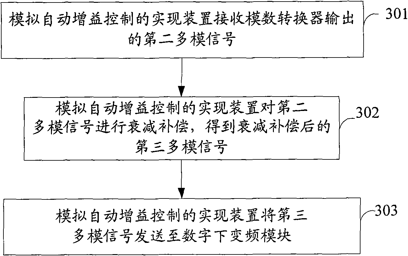
[0061] image 3 Shown is a schematic flow chart of an implementation method for simulating automatic gain control in an embodiment of the present invention, as image 3 As shown, this embodiment includes:

[0062] Step 301: The device for realizing the analog automatic gain control receives the ...


PUM


Abstract

The invention provides a method and a device for realizing simulated automatic gain control, which belong to the field of wireless communication. The method for realizing the simulated automatic gain control comprises the following steps that: the device for realizing the simulated automatic gain control receives a second multimode signal which is output by an analogue-and-digital converter; the device for realizing the simulated automatic gain control performs attenuation compensation on the second multimode signal to acquire a third multimode signal which is subjected to the attenuation compensation; and the device for realizing the simulated automatic gain control transmits the third multimode signal to a digital down-conversion module. By using the method and the device, the problem that a multimode signal cannot be precisely compensated is solved. The technical scheme can be widely applied to medium frequency chips.

Description

technical field [0001] The invention relates to the field of wireless communication, in particular to a method and device for realizing analog automatic gain control. Background technique [0002] When the IF chip is performing adjacent channel and blocking tests, when there is a large single tone, it may cause the analog to digital converter (Analog to Digital Converter, referred to as ADC) to overflow, resulting in signal compression, the baseband processing unit (Base Band Unit) , referred to as BBU) cannot be decoded normally, in order to avoid ADC overflow, it is necessary to perform analog automatic gain control (Automatic Gain Control, referred to as AGC), such as figure 1 Shown is a schematic diagram of analog automatic gain control in the prior art. AGC controls the signal attenuation of the RF digital attenuator and the intermediate frequency digital amplifier by calculating the power of the ADC output signal to avoid ADC overflow. After the gain control, the sign...

Claims


Application Information

Patent Timeline
Patent Type & Authority Applications(China)
IPC IPC(8): H04B7/005
Inventor 韩山秀
Owner SANECHIPS TECH CO LTD
Learn More