Deformation error compensation and target detection method for ship-borne radar array based on interference processing

An error compensation and radar array technology, which is used in the imaging detection of moving targets and the deformation error compensation of shipborne radar conformal arrays, which can solve problems such as target flicker, uncertain motion trajectory, and complex echo characteristics.

Active Publication Date: 2018-02-09
INST OF ELECTRONICS CHINESE ACAD OF SCI
View PDF8 Cites 2 Cited by
  • Summary
  • Abstract
  • Description
  • Claims
  • Application Information

AI Technical Summary

Problems solved by technology

Due to the small RCS of the moving target and the uncertain trajectory, its echo characteristics are more complex than those of stationary ground objects, and there are also phenomena such as target flickering during radar irradiation, coupled with background clutter, system noise, and human interference. etc., making moving target detection one of the difficulties in the field of radar imaging

Method used


Image

  • Deformation error compensation and target detection method for ship-borne radar array based on interference processing
  • Deformation error compensation and target detection method for ship-borne radar array based on interference processing
  • Deformation error compensation and target detection method for ship-borne radar array based on interference processing

Examples


no. 1 example

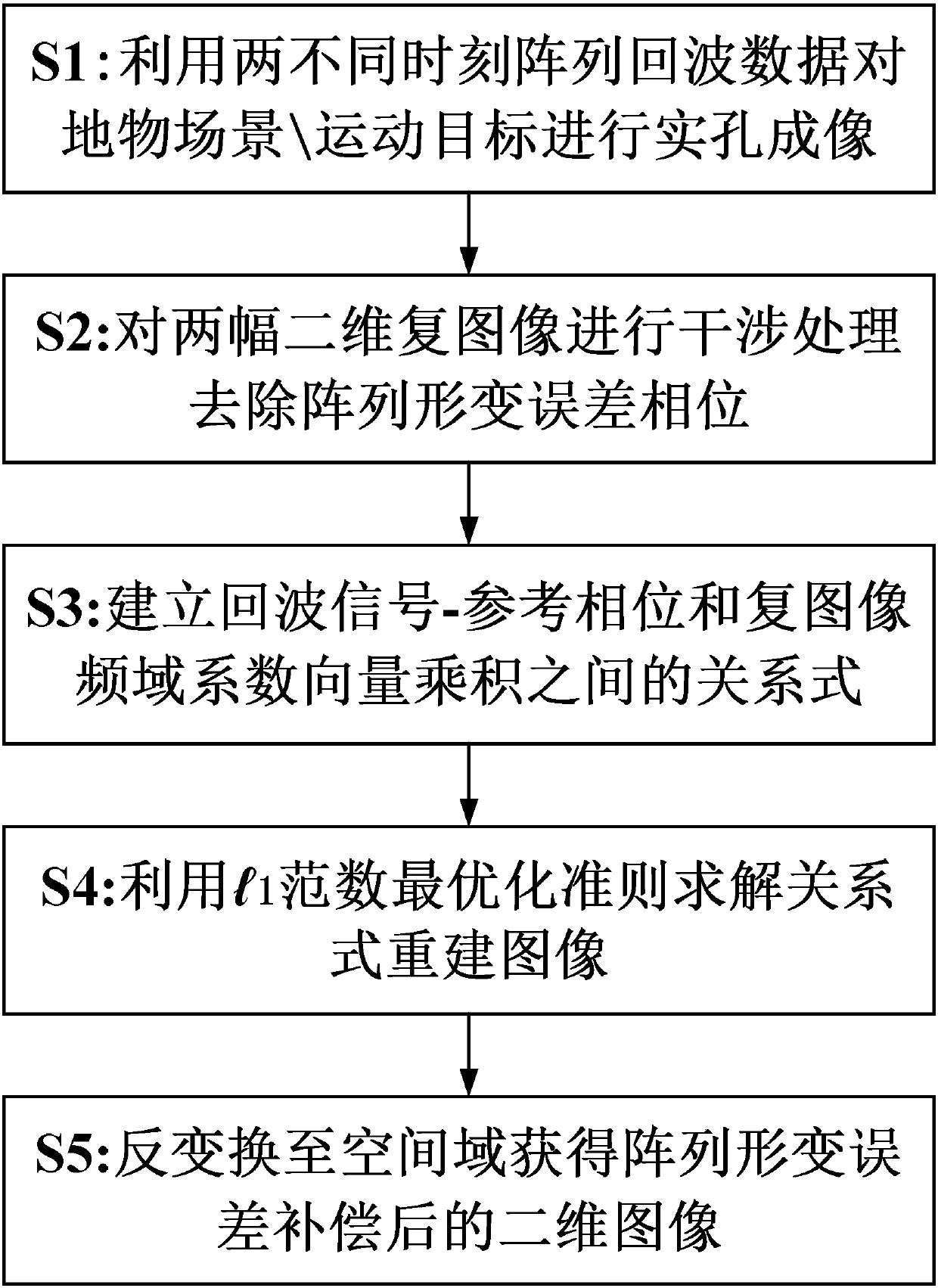
[0058] figure 2 It is a flow chart of a method for interferometrically processing shipborne radar array deformation error compensation and target detection according to the first embodiment of the present disclosure. like figure 2 As shown, the present embodiment is based on the interference processing shipborne radar array deformation error compensation and target detection method, including:

[0059] Step S1, when there is a deformation error in the array, use the array echo data at two adjacent different times of the shipborne radar to perform real-aperture imaging on the ground object scene or moving target, and obtain two two-dimensional complex images;

[0060] If the airship travels at speed v in step S1 a Moving in a straight line at a constant speed in the azimuth direction, the two adjacent moments of the boat-borne radar are respectively t 1 , t 2 ; In the ground imaging mode, t 1 , t 2 The slant range matrices of the radar and each scattering unit of the ta...


PUM


Abstract

The invention provides a deformation error compensation and target detection method for a ship-borne radar array based on interference processing, and the method comprises the steps: S1, carrying outthe real aperture imaging of a ground object scene or a moving object through two pieces of echo data of the array at the same moment; S2, carrying out the interference processing of two two-dimensional complex images, and removing a deformation error phase of the array; S3, building a relation between echo signal-reference phase and the product of frequency domain coefficient vectors of the complex images; S4, solving a relation reconstruction image through an l1 norm optimization criterion; S5, carrying out the inverse transformation of the image into a space domain, and obtaining a two-dimensional image of the array after the compensation of a deformation error. In a ground imaging mode, the method can achieve the frequency domain low-pass filtering of the two-dimensional spectrums of the complex images after interference, achieve the inverse transformation of the image into the space domain, and obtain the three-dimensional image of the ground object scene. The method obtains the ground imaging result with the good focusing effect, can remove the defocusing effect caused by the movement of the target, and improves the target detection performance of a radar.

Description

technical field [0001] The present disclosure relates to the fields of radar imaging processing and moving target detection, and in particular, to a method for compensating deformation error of a shipborne radar conformal array and a moving target imaging detection method based on interference processing and compressed sensing. Background technique [0002] Stratospheric airships have broad application prospects in the fields of high-altitude reconnaissance, regional early warning, and communication services because of their high-altitude resident characteristics. The huge volume of the stratospheric airship provides conditions for the use of large-scale antennas to achieve real-aperture imaging (see Li Liechen, Li Daojing, Huang Pingping. Real-aperture imaging of ship-borne sparse array antenna radar based on transform-domain sparse compressed sensing[J]. Acta Radar, 2016, 5(1):109-117). Due to the larger size of the airship, the size of the array antenna is also larger. ...

Claims


Application Information

Patent Timeline
Patent Type & Authority Applications(China)
IPC IPC(8): G01S7/41
CPCG01S7/41
Inventor 李道京田鹤
Owner INST OF ELECTRONICS CHINESE ACAD OF SCI
Why Eureka
Try Eureka