Method for monitoring chip groove depth and wafer
A groove depth and monitoring chip technology, which is applied in mechanical depth measurement, semiconductor/solid-state device components, semiconductor devices, etc., can solve problems such as poor accuracy and long time delay of chip groove depth
- Summary
- Abstract
- Description
- Claims
- Application Information
AI Technical Summary
Problems solved by technology
Method used
Image
Examples
Embodiment Construction
[0024] Embodiments of the present invention will be described in detail below in conjunction with the accompanying drawings.
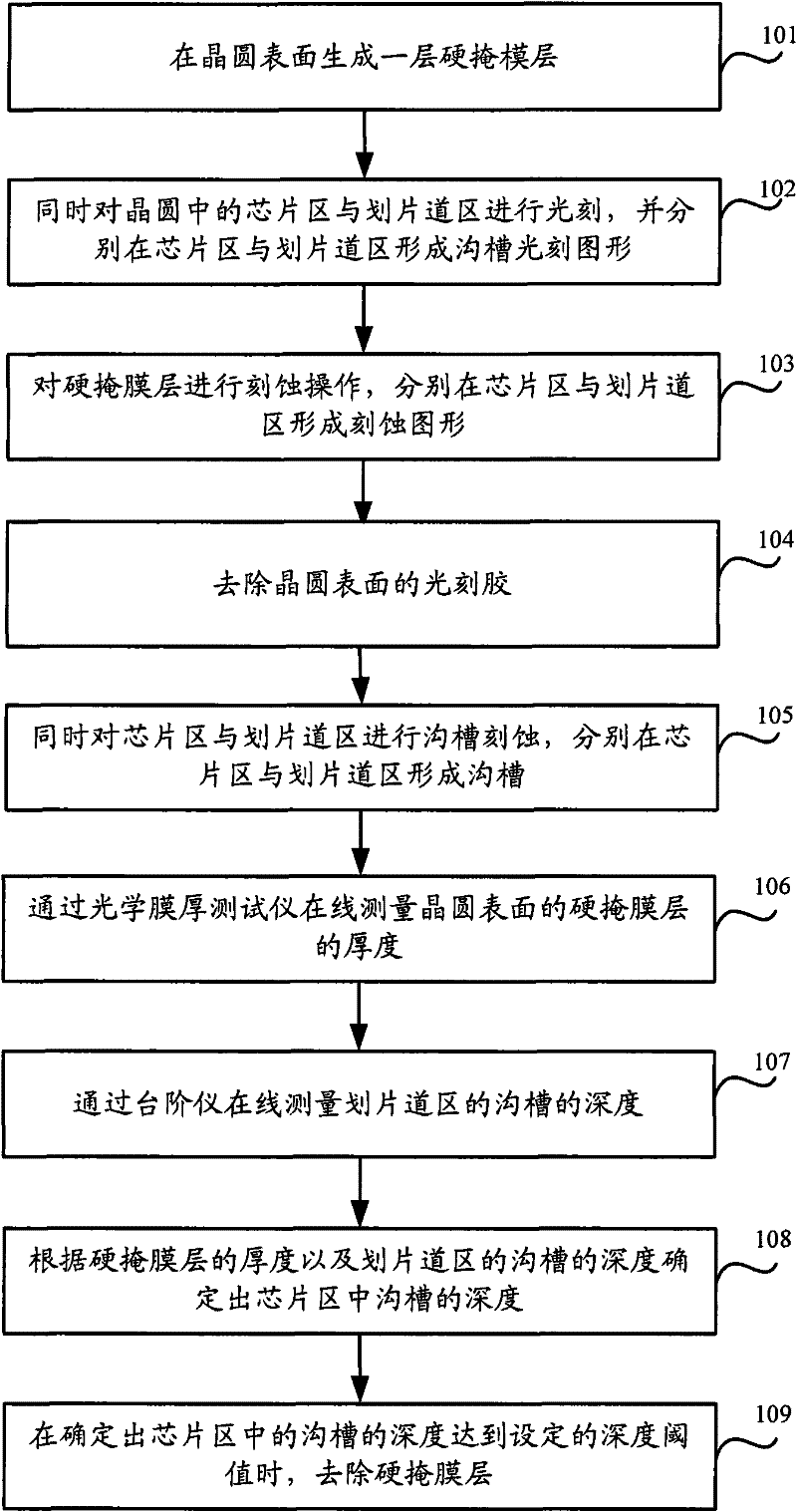
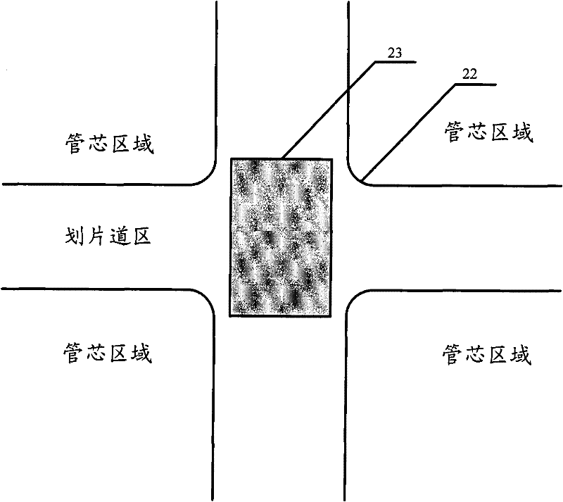
[0025] see figure 1 , is the flow chart of the method for realizing the real-time monitoring of the groove depth in the embodiment of the present invention. The module shaped as a cuboid (that is, the groove depth test module) is filled in the cross-staggered area of the wafer surface in advance. The polarity of the module is consistent with the chip area. The polarity of the trench photoresist layer is the same, and during the photolithography process, the cuboid module is a photolithography open area; the process includes the following steps:
[0026] Step 101 , forming a protective film, such as a hard mask layer 31 , on the surface of the wafer 21 .
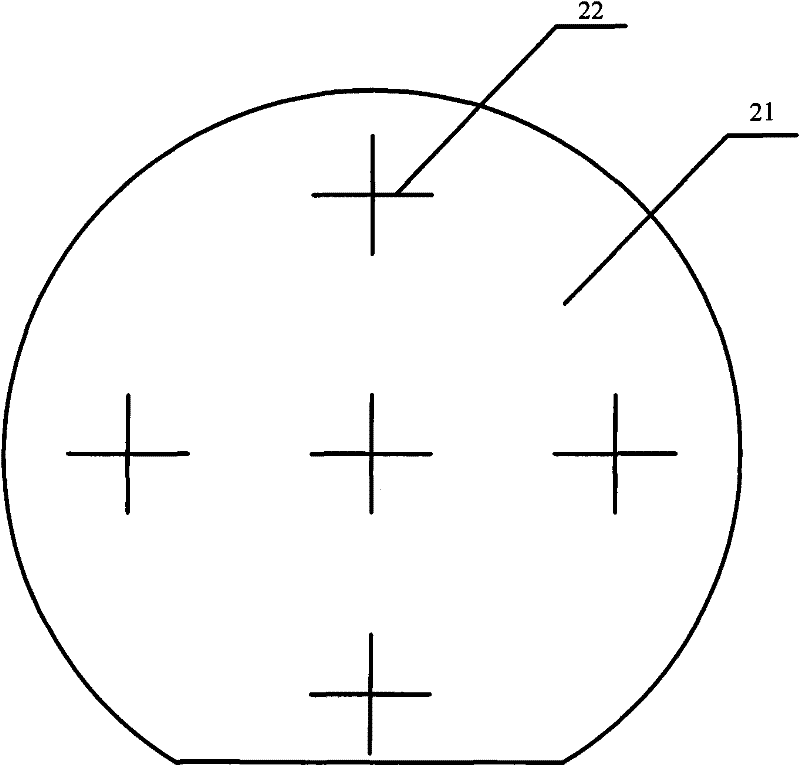
[0027] The structure of the wafer in this step is as follows Figure 2B As shown, is in the existing as Figure 2A All or part of the criss-cross region 22 of the wafer 21 shown is filled with t...
PUM
 Abstract
Description
Claims
Application Information
 - Generate Ideas
- Intellectual Property
- Life Sciences
- Materials
- Tech Scout
- Unparalleled Data Quality
- Higher Quality Content
- 60% Fewer Hallucinations
Browse by: Latest US Patents, China's latest patents, Technical Efficacy Thesaurus, Application Domain, Technology Topic, Popular Technical Reports.
© 2025 PatSnap. All rights reserved.Legal|Privacy policy|Modern Slavery Act Transparency Statement|Sitemap|About US| Contact US: help@patsnap.com


