
Local dimming driving method and device of liquid crystal display device

A local dimming, liquid crystal display technology, applied in optics, nonlinear optics, static indicators, etc., can solve the problems of large brightness deviation, defective products of LCD equipment, etc.

Active Publication Date: 2011-06-15
LG DISPLAY CO LTD
View PDF5 Cites 55 Cited by
  • Summary
  • Abstract
  • Description
  • Claims
  • Application Information

AI Technical Summary

Problems solved by technology

In addition, if the luminance deviation between blocks is large under the same gray scale, the LCD device may involve a defective product

Method used


Image

  • Local dimming driving method and device of liquid crystal display device
  • Local dimming driving method and device of liquid crystal display device
  • Local dimming driving method and device of liquid crystal display device

Examples


Embodiment Construction

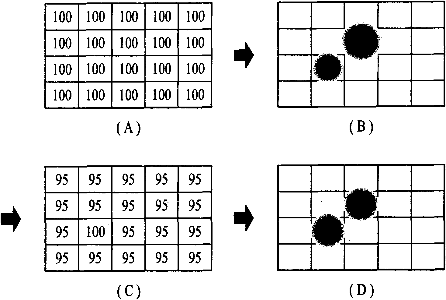
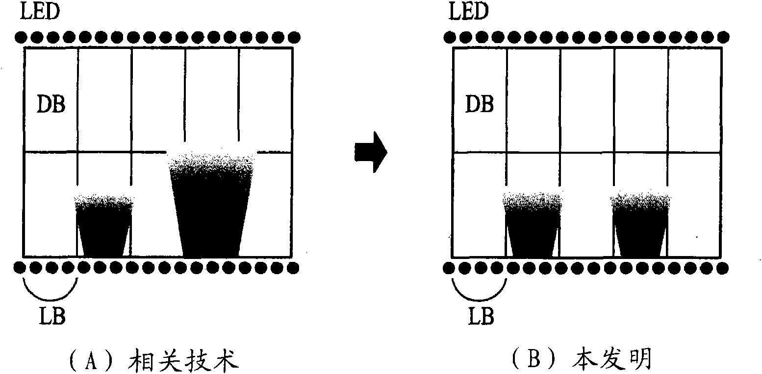
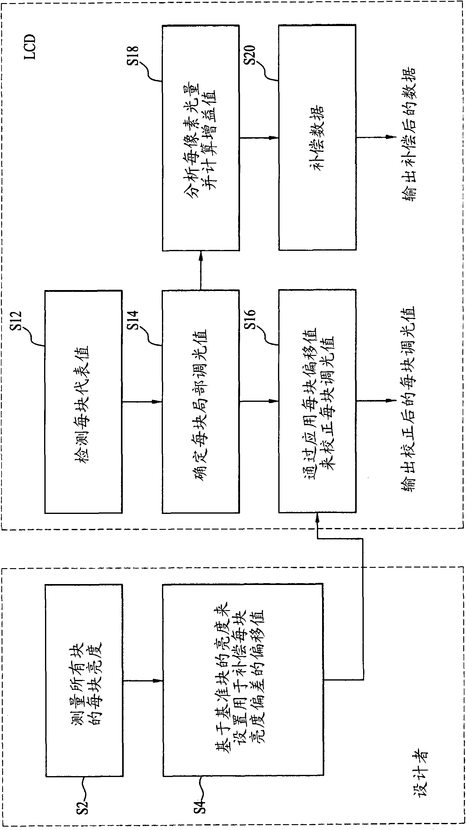
[0030] Reference will now be made in detail to preferred embodiments of the present invention, examples of which are illustrated in the accompanying drawings. figure 1 is a schematic diagram illustrating a local dimming driving method of a liquid crystal display (LCD) device according to an embodiment of the present invention.

[0031] figure 1 The illustrated direct type backlight unit includes, as a light source, an array of light emitting diodes (LEDs) that opposes the entire display area of ​​a liquid crystal panel and irradiates light. The LED array of the direct type backlight unit is driven in a state of being divided into a plurality of blocks LB, and the brightness thereof is controlled in units of block LB. In order to measure the luminance deviation between blocks LB due to characteristic differences between LEDs, assembly differences between tools, characteristic differences between optical sheets, or light leakage, such as figure 1 All the blocks LB of the backl...


PUM


Abstract

Disclosed herein is a local dimming driving method and device of an LCD device, which is capable of compensating for a luminance deviation between blocks. The local dimming driving method of the LCD device includes divisionally driving all of a plurality of blocks of a backlight unit using a maximum luminance signal and measuring luminance per block, setting one of the plurality of blocks as a reference block, detecting luminance deviations between the reference block and the residual blocks, and setting an offset value per block for compensating for the detected luminance deviations per block, analyzing an input image in units of blocks corresponding to the plurality of blocks of a backlight unit respectively, detecting a representative value per block, and determining a dimming value per block according to the representative value per block, correcting the dimming value per block using the offset value per block, and controlling the luminance of the backlight unit on a block-by-block basis using the corrected dimming value per block.

Description

technical field [0001] The present invention relates to a liquid crystal display (LCD) device, and more particularly, to a local dimming driving method and device for an LCD device capable of compensating for brightness deviation between blocks. Background technique [0002] This application claims the benefit of Korean Patent Application No. 10-2009-0124281 filed December 14, 2009, the contents of which are hereby incorporated by reference as if fully set forth herein. [0003] Recently, as an image display device, a flat panel display device such as a liquid crystal display (LCD) device, a plasma display panel (PDP) device, or an organic light emitting diode (OLED) device is mainly used. [0004] The LCD device includes: a liquid crystal panel for displaying images using a pixel matrix using electrical and optical characteristics of liquid crystals having anisotropy in refractive index and dielectric constant; a driving circuit for driving the liquid crystal panel; and a b...

Claims


Application Information

Patent Timeline
Patent Type & Authority Applications(China)
IPC IPC(8): G09G3/36G02F1/133
CPCG09G2360/16G09G2320/0233G09G2320/0646G09G2360/145G09G3/3426G09G2320/064G02F1/133G09G3/36
Inventor 洪熙政吴义烈李是勋安熙元
Owner LG DISPLAY CO LTD
Learn More