
Laser projection system

A laser projection and laser technology, applied in optics, instruments, projection devices, etc., can solve the problems of reducing the color contrast of the imaging picture and lengthening the distance.

Inactive Publication Date: 2011-06-15
ALVIS TECH
View PDF9 Cites 10 Cited by
  • Summary
  • Abstract
  • Description
  • Claims
  • Application Information

AI Technical Summary

Problems solved by technology

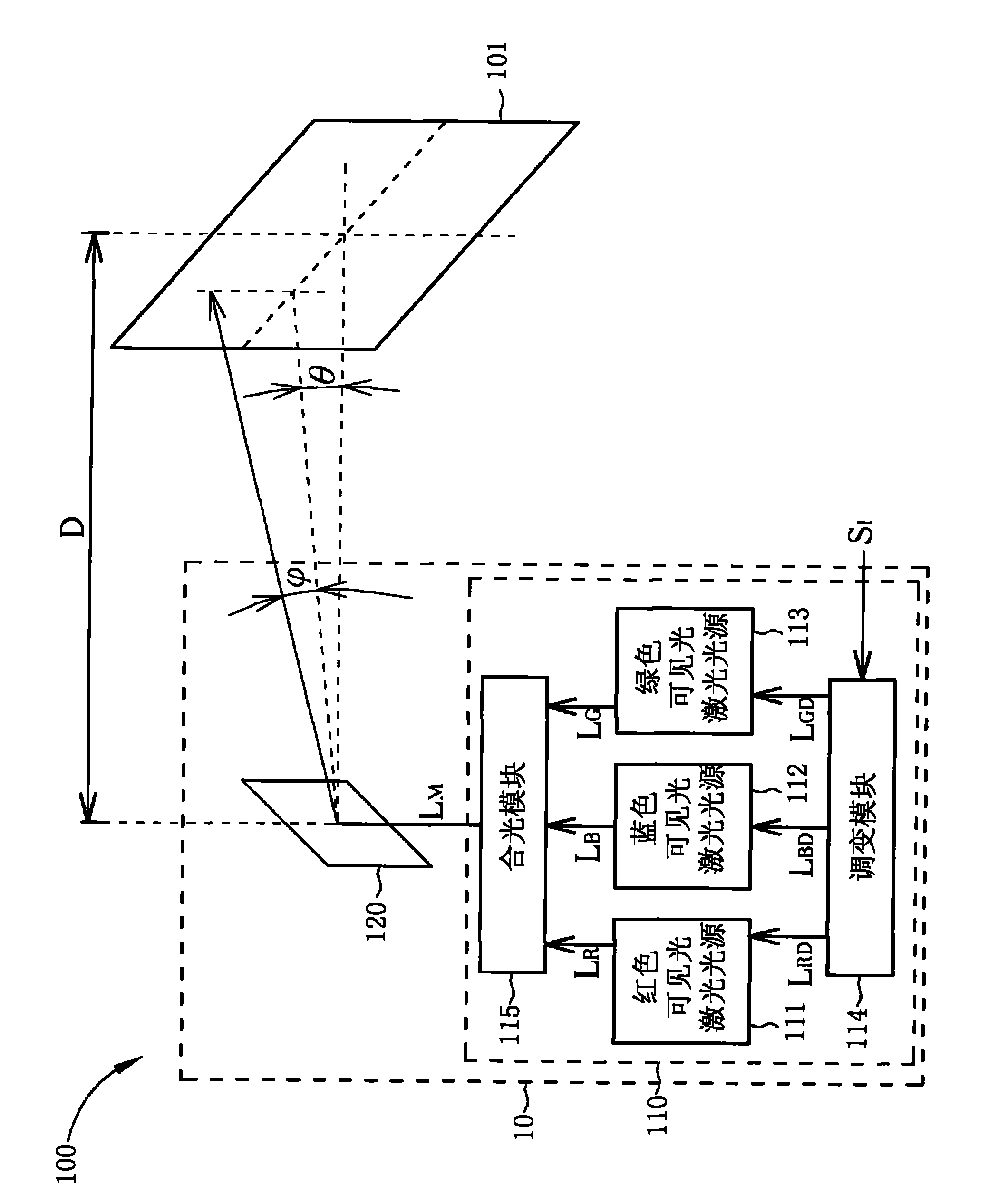
[0004] The above-mentioned laser projection technology has the following disadvantages: First, in order to use the scattering principle to form an image, the display screen is opaque, so this imaging technology is limited in applications that require a transparent display screen, such as projecting images on driving The vehicle head-up display of the windshield in front of the seat; second, due to the deflection angle θ of the rotating plane mirror module and limited, the distance D between the projection screen and the laser projector must be elongated to produce a larger projection screen; third, when the visible light in the background light hits the display screen, it will also be scattered by the screen or The reflection is received by the observer, which reduces the color contrast of the imaging picture

Method used


Image

  • Laser projection system
  • Laser projection system
  • Laser projection system

Examples


Embodiment 1

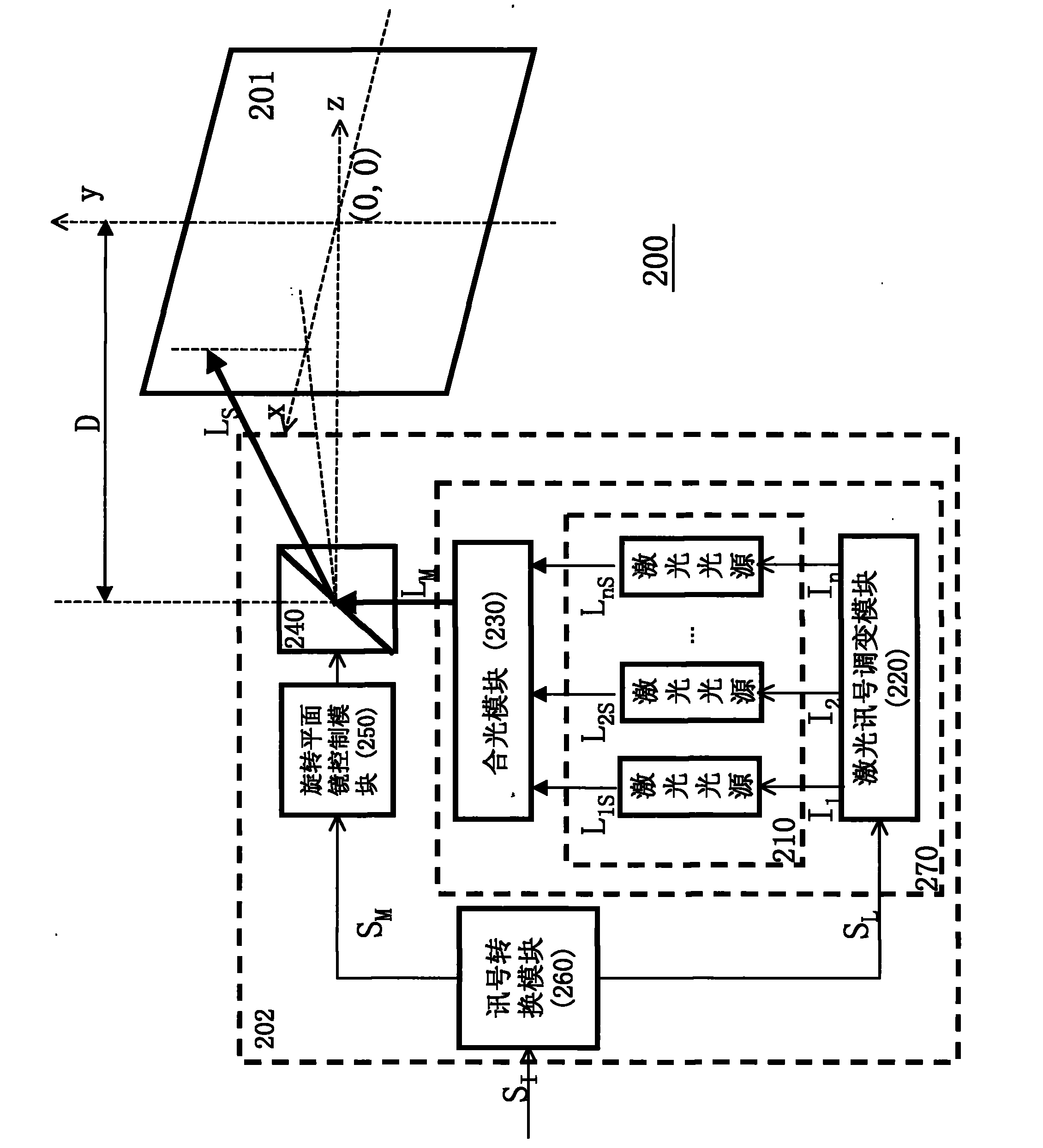
[0039] refer to figure 2 , which is a schematic diagram of a laser projection system 200 according to Embodiment 1 of the present invention; the laser projection system 200 includes a projection screen 201 and a laser projector 202 . The laser projector 202 is used for the image signal S based on a single picture or a dynamic picture I , to project the image onto the projection screen 201 . The laser projector 202 includes a laser light source module 210 , a laser signal modulation module 220 , a light combining module 230 , a rotating plane mirror module 240 , a rotating plane mirror control module 250 and a signal conversion module 260 . In addition, the structure composed of the laser light source module 210 , the laser signal modulation module 220 and the light combination module 230 is defined as the laser optical module 270 for the convenience of discussion below.

[0040] The projection screen 201 is provided with a luminescent layer, and the luminescent layer is pro...

Embodiment 2

[0097] refer to image 3 , which is a schematic diagram of a laser projection system 300 according to Embodiment 2 of the present invention; the laser projection system 300 includes a projection screen 301 and a laser projector 302 . The laser projector 302 is used for the image signal S based on a single picture or a dynamic picture I , to project the image onto the projection screen 301 . The laser projector 302 includes a laser light source module 310 , a laser signal modulation module 320 , a light combining module 330 , a rotating plane mirror module 340 , a rotating plane mirror control module 350 , and a signal conversion module 360 ​​. In addition, a laser optical module 370 is defined, which includes a laser light source module 310 , a laser signal modulation module 320 and an optical combining module 330 for the convenience of discussion below.

[0098] Among them, the structure and working principle of the laser signal modulation module 320, the light combination ...

Embodiment 3

[0121] refer to Figure 4 , which is a schematic diagram of a laser projection system 400 according to Embodiment 3 of the present invention; the laser projection system 400 includes a projection screen 401 and a laser projector 402 . The laser projector 402 is used to base on the image signal S of a single picture or a dynamic picture I , to project the image onto the projection screen 401 . The laser projector 402 includes a laser light source module 410 , a laser signal modulation module 420 , a rotating plane mirror module 440 , a rotating plane mirror control module 450 , and a signal conversion module 460 . In addition, a laser optical module 470 is defined, which includes a laser light source module 410 and a laser signal modulation module 420 for the convenience of discussion below.

[0122] Wherein, the structure and working principle of the rotating plane mirror module 440, the rotating plane mirror control module 450, and the signal conversion module 460 are simil...


PUM

PropertyMeasurementUnit
Wavelengthaaaaaaaaaa

Abstract

The invention relates to a laser projection system which comprises a projection screen and a laser projector, wherein the projection screen comprises at least one light emitting layer, and the light emitting layer comprises at least one light emitting substance which can be excited to generate excited light in another wavelength range when irradiated by exciting light in a wavelength range; the transverse distances between the light emitting substances parallel to the plane of the projection screen are far shorter than the cross section diameter of a laser beam; and the laser projector comprises a laser light source module, a laser signal modulation module, a light combining module, a rotary plane mirror module, a rotary plane mirror control module and a signal conversion module. In the invention, exciting laser is generated according to an image signal of a single picture or a dynamic picture and projected to the matched projection screen to generate an image so as to ensure that a high-recognition projection picture can be presented on the projection screen under natural light environment through a nearly transparent effect, and a user can see the projected picture and an objectbehind the projection screen at the same time so as to promote the use efficiency and the application range of the laser projection system.

Description

technical field [0001] The present invention relates to a laser projection system, especially a laser projector that uses a single image or a dynamic image signal to generate excitation laser light and project it onto a matching projection screen to generate an image. The projection screen can present a highly recognizable projection picture with almost transparent effect under the environment of natural light, so that people can see the projection picture and see the objects behind the projection screen at the same time. Background technique [0002] There are many previous technologies related to the design of laser projection systems, including US6,986,581, US7,090,355, US7,182,467, US7,213,923, US7,452,082, etc., which disclose related technologies of films used as projection screens; Including US6,843,568 and its references (References Cited) and other public information are related technologies for disclosing laser scanning display devices (laser scanning display); for...

Claims


Application Information

Patent Timeline
IPC IPC(8): G03B21/56G03B21/20G03B21/28
Inventor 陈致晓陈国仁温明华
Owner ALVIS TECH
Learn More