
Preparation method and pressing device for radiation-oriented magnet ring or multipolar magnet ring

A radiation orientation, multi-pole magnetic ring technology, applied in the direction of inductance/transformer/magnet manufacturing, inorganic material magnetism, electrical components, etc., can solve the problem of uneven shrinkage of the magnetic ring, achieve magnetic uniformity, improve magnetic performance, The effect of increasing the degree of orientation

Active Publication Date: 2014-06-25
BEIJING ZHONG KE SAN HUAN HI TECH
View PDF11 Cites 0 Cited by
  • Summary
  • Abstract
  • Description
  • Claims
  • Application Information

AI Technical Summary

Problems solved by technology

[0006] The purpose of the present invention is to provide a method for preparing a radiation-oriented magnetic ring or a multi-pole magnetic ring and its pressing equipment, which can further improve the orientation degree of the magnetic ring without changing the mold structure, so as to improve the magnetic performance of the magnetic ring At the same time, it can effectively solve the problem of sintering cracking caused by uneven shrinkage of the magnetic ring due to internal stress during the sintering process, and can significantly improve the sintering yield of the magnetic ring

Method used


Image

  • Preparation method and pressing device for radiation-oriented magnet ring or multipolar magnet ring
  • Preparation method and pressing device for radiation-oriented magnet ring or multipolar magnet ring
  • Preparation method and pressing device for radiation-oriented magnet ring or multipolar magnet ring

Examples


preparation example Construction

[0016] According to the present invention, the preparation method of radiation orientation magnetic ring and multi-pole magnetic ring comprises:

[0017] (1) Preparation of alloy ingots: the raw materials are conventionally smelted into alloy ingots in vacuum or inert gas;

[0018] (2) Alloy ingot crushing: coarsely crushing and hydrogen crushing the alloy ingot in an inert atmosphere to obtain a powder with a particle size of several hundred microns; add 0.01 to 1 wt% of an antioxidant to the hydrogen crushed powder to mix 2 Hours; use jet mill to pulverize the coarse powder after hydrogen crushing under nitrogen environment to obtain alloy powder with average particle size of about 4m and uniform particle size distribution;

[0019] (3) Powder pre-orientation: Fill the powder into the mold cavity of the molding press, and perform pre-orientation operation on the powder; change the yoke to four movable parts along the circumferential direction, and move them separately during...

Embodiment 1

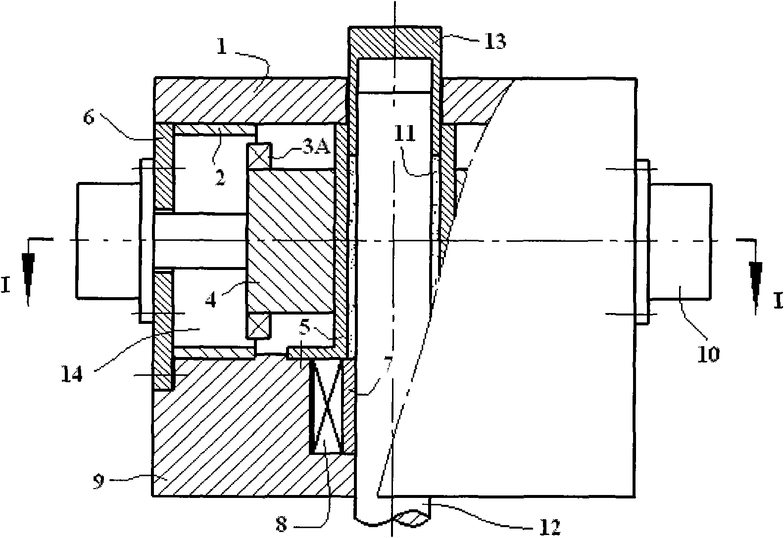
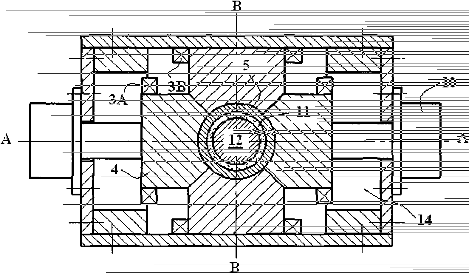
[0029] When powder is loaded, the two yokes 4 in the direction of length A-A and the two yokes 4 in the direction of width B-B form a complete ring. After the powder is loaded, the upper pressure head drops and the iron core closes. Move the two yokes 4 along the A-A direction for 50-150mm, and then, the excitation coil 3B generates a magnetic field with the same polarity along the B-B direction to pre-orient the powder for the first time, and the magnetic field in the mold cavity is 0.8-2.0T After the orientation is completed, push back the two yokes 4 in the direction of length A-A to their original positions; then move the two yokes 4 in the direction of width B-B for 50-150mm along the direction of B-B, and the excitation coil 3A generates a magnetic field with the same polarity , the direction is along the A-A direction, and the magnetic field in the mold cavity is 0.8-2.0T. After the orientation is completed, the yoke 4 in the width B-B direction is pushed back to the ori...

Embodiment 2

[0032] When powder is loaded, the two yokes 4 in the direction of length A-A and the two yokes 4 in the direction of width B-B form a complete ring. After the powder is loaded, the upper pressure head drops and the iron core closes. Pre-magnetize the pulsed magnetic field along the C-C direction (that is, the height direction), and then press the magnetic ring under the radiation orientation magnetic field.

[0033] In order to solve the cracking problem in the sintering process of the magnetic ring, after the radiation-oriented magnetic ring is pressed and isostatically pressed, it is placed in a protective gas atmosphere (such as an inert gas Ar 2 or N 2 ) or in a vacuum state, the inner wall of the magnetic ring is ground as a whole, and after the inner diameter is ground to 0.1-1 mm, the sintering aging heat treatment is performed.

[0034] The present invention also provides a pressing device for preparing radiation-oriented magnetic rings and multi-pole magnetic rings. ...


PUM


Abstract

The invention provides a preparation method for a radiation-oriented magnet ring or a multipolar magnet ring, which comprises the following operation steps of: preparing an alloy ingot, cracking the alloy ingot, pressing under a radiation-oriented magnet field, sintering the magnet ring and subsequently machining and is characterized in that a powder pre-orientation step is also arranged before the step of pressing under the radiation-oriented magnet field, powder is first filled in a die cavity of a forming press, and pre-orientation operation is then carried out on the powder. Before the step of sintering the magnet ring, a step of preprocessing a blank is also arranged. Preprocessing operation is carried out on the blank magnet ring under protective atmosphere. The orientation degree of the magnet ring can be further improved under the condition that the die structure is not changed, so that the purpose for improving the magnetic performance of the magnet ring is achieved. Meanwhile, sintering crack problems resulting from nonuniform contraction caused by the internal stress of the magnet ring in the sintering process can be effectively solved, and the sintering finished product rate of the magnet ring can be obviously improved.

Description

technical field [0001] The invention relates to a method for preparing a radiation-oriented magnetic ring or a multi-pole magnetic ring and its pressing equipment, in particular to a method for preparing a radiation-oriented rare earth permanent magnetic ring or a multi-pole rare earth permanent magnetic ring and its pressing equipment. [0002] In this specification, the term "radiation orientation magnetic ring" means that the magnetization direction is radial along the radial direction of the ring, and N poles and S poles are formed on the inner and outer sides of the magnetic ring; [0003] The term "radial multi-pole ring" refers to the special pulse treatment of the radial orientation ring, so that the inner and outer sides of the magnetic ring form multiple pairs of N poles and S poles. Background technique [0004] In the prior art of preparing radiation-oriented magnetic rings and multi-pole magnetic rings, the principle of homosexual repulsion of magnetic poles is ...

Claims


Application Information

Patent Timeline
Patent Type & Authority Patents(China)
IPC IPC(8): H01F41/02H01F1/08
Inventor 陈国安王浩颉王湛钮萼李正饶晓雷胡伯平
Owner BEIJING ZHONG KE SAN HUAN HI TECH
Learn More