
Composite fireproof door

A technology for fire doors and door frames, applied in fire doors, sealing devices, etc., can solve problems such as affecting fire protection effect, wasting wood, and wasting wood resources.

Inactive Publication Date: 2011-06-08
邓学开
View PDF0 Cites 6 Cited by
  • Summary
  • Abstract
  • Description
  • Claims
  • Application Information

AI Technical Summary

Problems solved by technology

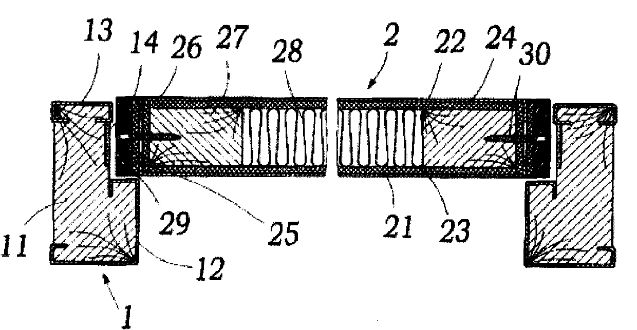
[0003] The aforementioned existing fireproof and insulating doors have several shortcomings that need to be improved. For example, the L-shaped corner post 11 needs to cut off the corners during manufacture, so a lot of wood will be wasted, resulting in a waste of wood resources; the stainless steel plate 12 , 13 are bent many times, and the wooden corner post 11 needs to be pre-grooved for steel plate embedding, and the process is quite complicated; and inserting the stainless steel guard frame 12, 13 into the corner post 11 will destroy the chord of the corner post 11. When the fire steel plate is heated, instead, the heat source is quickly introduced into the wooden corner post 11 to speed up the carbonization time and increase the carbonization degree of the wooden corner post 11, seriously affecting its fireproof effect
In addition, the stainless steel door panels 21 and 22 of the above-mentioned case need to be bent relatively, and strong fireproof foam heat insulation panels 25 and 26 are arranged inside and outside the bent parts, and then clamped with wooden structural panels 27 and fastened with screws 30. The fire-proof boards used are scattered and the structure lacks integrity. This kind of structure may have problems with the stability of the body

Method used


Image

  • Composite fireproof door
  • Composite fireproof door
  • Composite fireproof door

Examples


Embodiment Construction

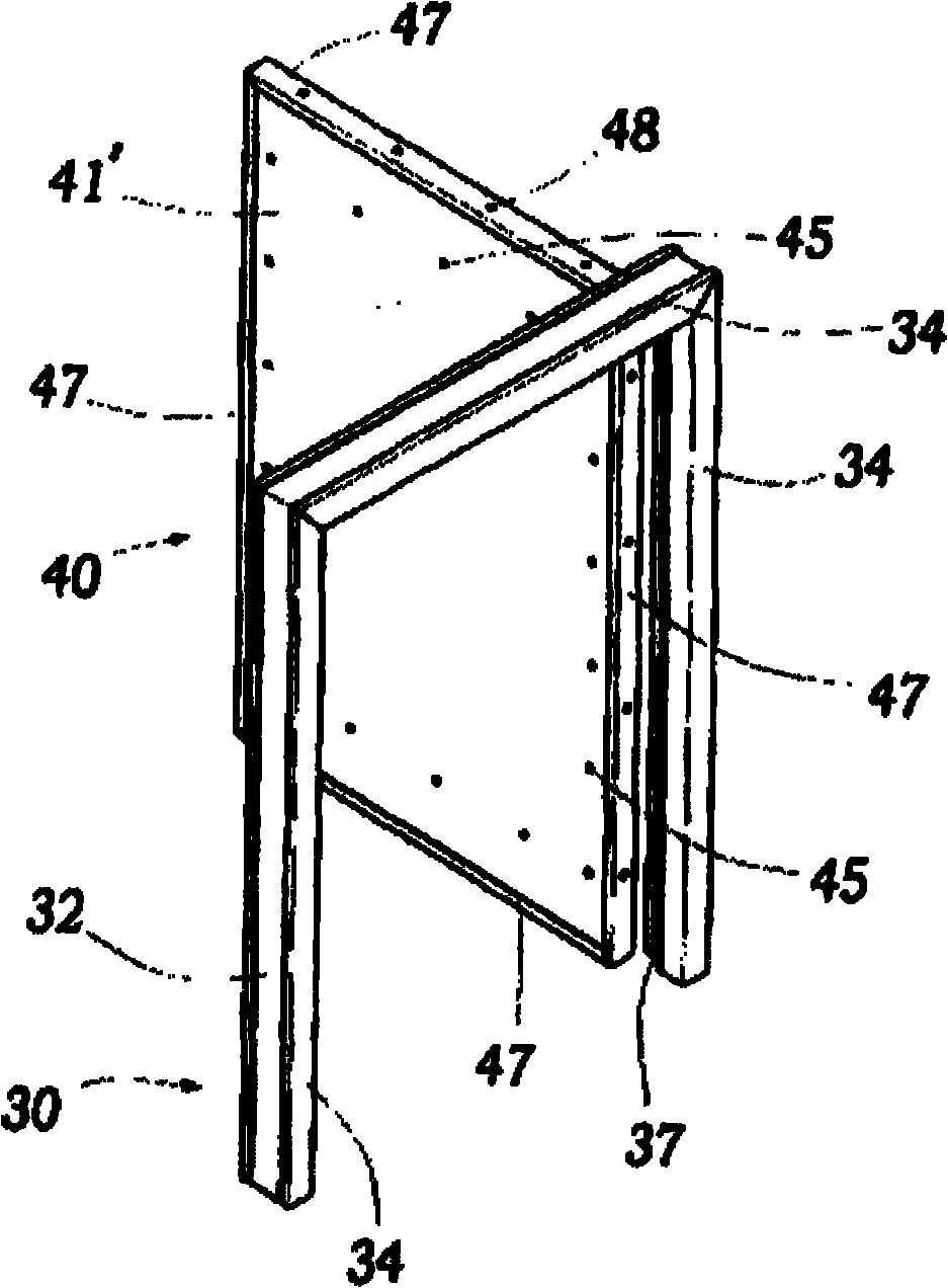
[0016] Please refer to the Figure 2 to Figure 5 , The composite fire door structure of the present invention mainly includes a composite fire door frame 30 and a composite fire door 40, and the composite fire door 40 is fixed on the composite fire door frame 30 by hinges.

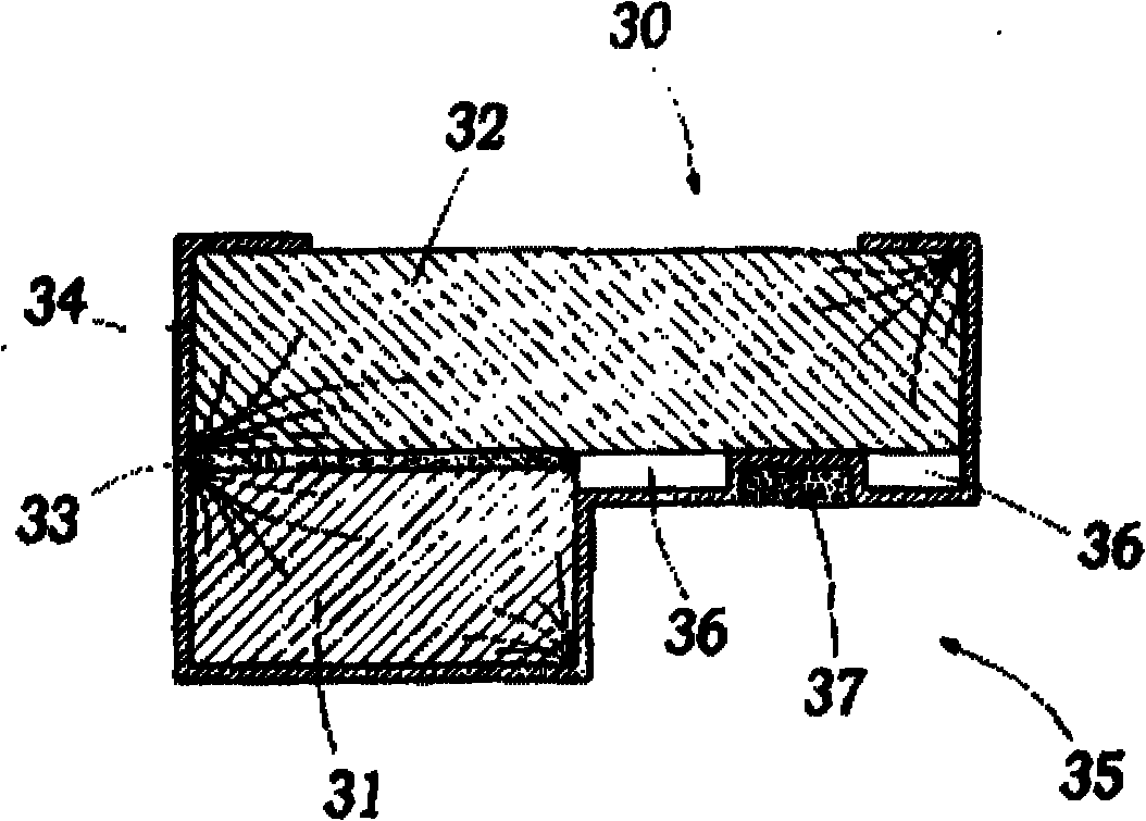
[0017] The composite fireproof door frame 30 is composed of left, right and upper frames. The frame system is composed of two solid wood angles (132) with equal thickness and different widths. image 3 The L-shaped door frame 30 is shown.

[0018] Composite fire door 40 has front and back two steel plates 4141 ', between two steel plates 4141 ', the fixed fire prevention plate is sandwiched. The fire-proof board is constructed with a plywood 4242' on the inner surface of the two steel plates 4141', the plywood 4242' is an ordinary wood plywood, and a fireproof board 4343' is arranged on the inner surface of the two plywood 4242', and the fireproof board 4343' is magnesium oxide board or calcium silicate ...


PUM


Abstract

The invention relates to a composite fireproof door. A composite fireproof door frame is formed by bonding two solid wood angle sections with unequal widths by using a heat insulating expansion adhesive; a protective steel plate is coated along the outer edge of each solid wood angle section; a predetermined distance exists between a part of the protective steel plate and each solid wood angle section so as to form an air heat insulating chamber; an expansion sealing strip is embedded into the protective steel plate relative to the edge of the composite fireproof door; the composite fireproof door is provided with two steel plates; the inner surfaces of the two steel plates are provided with a splint and a fireproof plate respectively; two side spaces between the two fireproof plates are provided with a wood structural material respectively; the steel plates, the splints and the fireproof plates are fixed on the wood structural materials through screws; spaces between the two wood structural materials and the two fireproof plates are filled with heat insulating materials; and the periphery of the composite fireproof door is coated with a C-shaped sheathing steel sheet and is fixed on the wood structural materials by screws. By the structure, fire prevention, heat insulating and smoke and fire intrusion prevention effects are achieved under the condition of fire.

Description

【Technical field】 [0001] The invention relates to a fireproof building material, in particular to a composite fireproof door. 【Background technique】 [0002] Such as figure 1 As shown, it is the existing composite fire-proof and heat-insulating door structure. The patent is mainly composed of a door frame 1 and a composite fire door 2. The door frame is composed of left, right and upper frames. The fire-resistant expansion side strip 14 is formed, and one end angle of the corner post 11 is a concave gap, and there is a side strip groove seat opposite to the composite fire door 2, and the fire-proof expansion side strip 14 is embedded, and the front end angle of the corner post 11 is and the rear end are embedded with stainless steel protective frames 12, 13, and the contact surfaces of the front and rear end protective frames and corner columns are lined with fireproof and heat-insulating expansion films; the composite fire door 2 is connected to the door frame side by hin...

Claims


Application Information

Patent Timeline
IPC IPC(8): E06B5/16E06B7/22
Inventor 邓学开
Owner 邓学开
Learn More