
Light guide body covered with optical membrane

A technology of an optical film layer and a light guide body is applied in the field of light guide bodies, and can solve the problems of high cost, limited application surface of the light guide plate, complicated manufacturing process, etc.

Active Publication Date: 2011-06-01
江苏乐士源新能源科技有限公司
View PDF5 Cites 15 Cited by
  • Summary
  • Abstract
  • Description
  • Claims
  • Application Information

AI Technical Summary

Problems solved by technology

Although the light guide efficiency can be maximized by optimizing the design of the scattering mechanism layer and the scattering unit, since the light will inevitably transmit from the main surface opposite to the main exit surface and become invalid exit light, there is a principle of its light guide efficiency. upper limit and cannot reach higher
[0004] The current light guide is limited to plate-shaped light guide plates. The light guide technology is made by mechanical engraving, printing dots, laser engraving, and special light guide plate structures. There are still complex manufacturing processes, high costs, and low cost performance. It is difficult to break through the upper limit of the above-mentioned theoretical light guide efficiency, and at the same time, the plate-shaped light guide body, that is, the application surface of the light guide plate, is also subject to certain restrictions.

Method used


Image

  • Light guide body covered with optical membrane
  • Light guide body covered with optical membrane
  • Light guide body covered with optical membrane

Examples


Embodiment 1

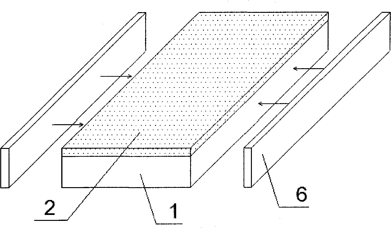
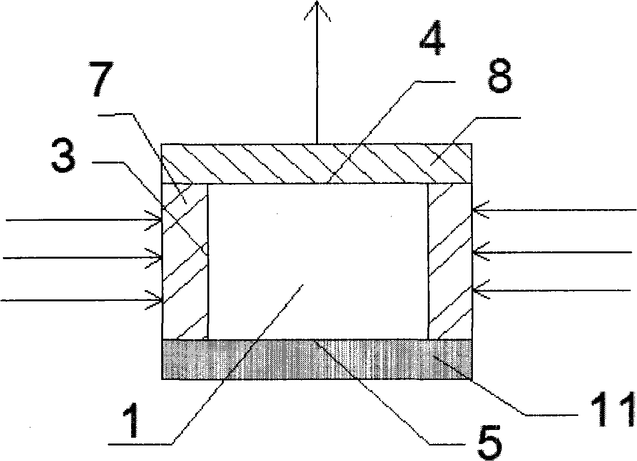
[0088] Embodiment 1: A side-entry structural light guide, such as Figure 1a The light source 6 uses 90 pieces of 3528SMD patch LEDs; it is welded on an aluminum-based printed board with a length of 165mm and a width of 10mm, and is arranged on the incident surface 3 of the solid geometric body 1. The solid geometric body 1 of the light guide is 160mm long, 65mm wide, and The PMMA plate with a thickness of 6mm has a geometric shape of a hexahedron in a solid polyhedron made of PMMA material, and has six outer surfaces; the light source 6 is arranged on two opposite sides of the hexahedron, and this side is the incident surface 3 , so there are two incident surfaces 3 in the figure, and the remaining two sides are reflective surfaces 5 . One parallel outer surface of the hexahedron is the light-emitting surface 4, and the other parallel outer surface is the reflective surface 5. This light guide is a side-entry structural light guide with incident light from the side and light o...

Embodiment 2

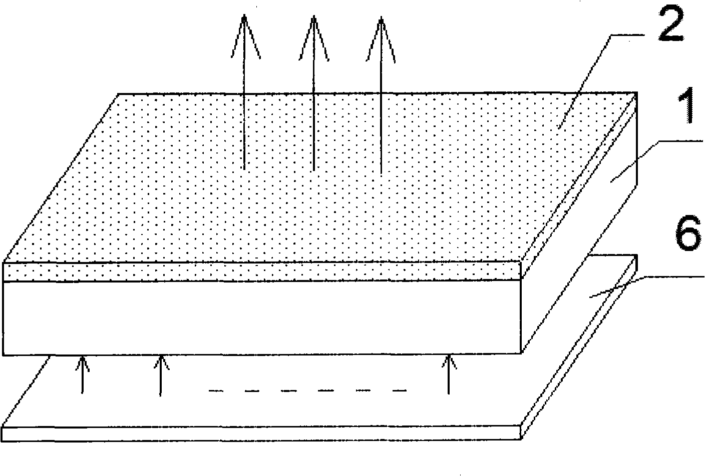
[0093] Embodiment 2: a kind of direct type structure light guide body, such as Figure 2a : The solid geometric body 1 of the light guide plate is a PMMA plate, and its geometric shape is a six-sided geometric body in a solid polyhedron, with six outer surfaces in total. The light source 6 is arranged on a parallel surface of the solid geometric body 1, then this parallel surface is the incident surface 3, and the other parallel surface is the light-emitting surface 4, (the rest of the sides are all reflective surfaces 5), the light guide plate is based on a parallel surface of the geometric body The incident light and the light exiting from another parallel surface of the geometric body is the direct-type structured light guide plate. Its light-emitting surface 4 is the light-emitting surface 4 of a direct-down structure light guide plate, which needs to be covered with a diffusion film layer 9, such as Figure 2b : In this embodiment, high-purity silica powder with a partic...

Embodiment 3

[0098] Embodiment 3: A tubular light guide plate, such as Figure 3a : The solid geometric body 1 of the light guide is a PMMA pipe, and its geometric shape is a ring-shaped geometric body in a solid rotating body. The outer surface is composed of two inner and outer curved surfaces and two bottom surfaces. The light source 6 is arranged on a bottom surface of the ring-shaped geometric body, and this bottom surface is the incident surface 3, so there is only one incident surface 3 in the figure, and the other bottom surface is the reflective surface 5. The inner curved surface of the annular geometry is also the reflective surface 5 . The outer curved surface of the ring-shaped geometric body is the light-emitting surface 4 , and the light guide is a side-entry structural light guide plate in which light is incident on a bottom surface of the ring-shaped geometric body and light is emitted from the outer curved surface of the ring-shaped geometric body. Such as Figure 3b : ...


PUM

PropertyMeasurementUnit
Thicknessaaaaaaaaaa
Thicknessaaaaaaaaaa
Thicknessaaaaaaaaaa

Abstract

The invention discloses a light guide body covered with an optical membrane. The light guide body comprises a transparent solid geometry and an optical membrane and is characterized in that: the optical membrane is covered on the outer surface of the transparent sold geometry with the thickness of over 1 mm; in the solid geometry, at least one outer surface is an incident face; at least one outersurface is a light emitting surface; the solid geometry at least comprises a medium membrane material optical membrane layer of submicron particles or nano-particles; and the thickness of the membrane is between 91 nm and 5 mm. The invention aims to cover a matched optical membrane by a well-known coating method on the outer surfaces of sold geometries with different optical functions, so that the light guide body with higher efficiency and more functions is possible to realize. The light guide body can match a light-emitting diode (LED) light source for using, match other various light sources to be used in lighting and display light fittings and backlight, and also can be made into purification light fittings, sterilization light fittings, phototherapy light fittings, plant illuminationlight fittings and the like. Along with the development of an electronic membrane technology, more commercial opportunities for light guide body application products can be exploited.

Description

technical field [0001] The invention relates to a light guide body, in particular to a light guide body covered with an optical film layer and a manufacturing method, which can be widely used in various technical fields related to surface light sources such as display, lighting, and backlight source. Background technique [0002] Disclosed by Chinese invention patent CN100508222C: the energy utilization rate of surface light source devices based on light-emitting diodes that have appeared is still relatively low. On the one hand, because the LED manufacturing technology itself is still developing, there is still a lot of room for improvement in its power efficiency (Wall-Plug Efficiency); on the other hand, the secondary packaging efficiency ( Secondary efficiency for short) is still relatively low, and the low light guide efficiency of the light guide plate in the light guide body is an important reason. The light guide efficiency of the light guide plate is defined as the...

Claims


Application Information

Patent Timeline
IPC IPC(8): G02B6/00G02B5/02G02B1/10G02B1/11F21V8/00G02B1/16
Inventor 吴明番柴永芳
Owner 江苏乐士源新能源科技有限公司
Learn More