
Optical member for photomask and method for manufacturing the optical member

A technology of optical components and manufacturing methods, applied to optics, manufacturing tools, glass manufacturing equipment, etc., can solve problems that cannot be said to be sufficient transmittance

Active Publication Date: 2011-05-18
NIKON CORP
View PDF3 Cites 2 Cited by
  • Summary
  • Abstract
  • Description
  • Claims
  • Application Information

AI Technical Summary

Problems solved by technology

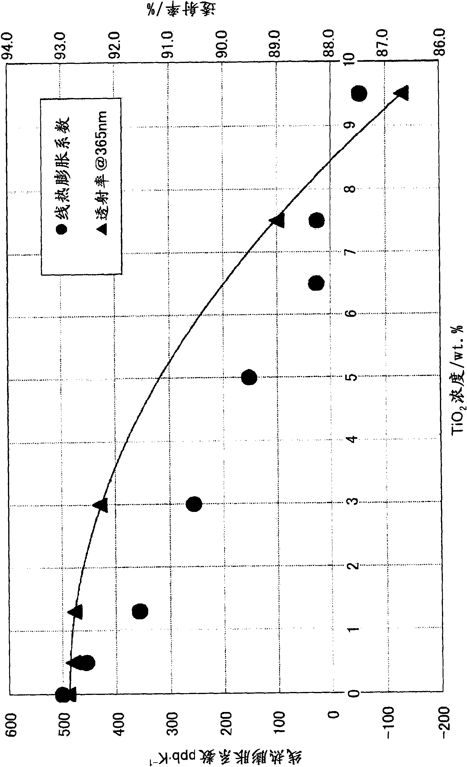
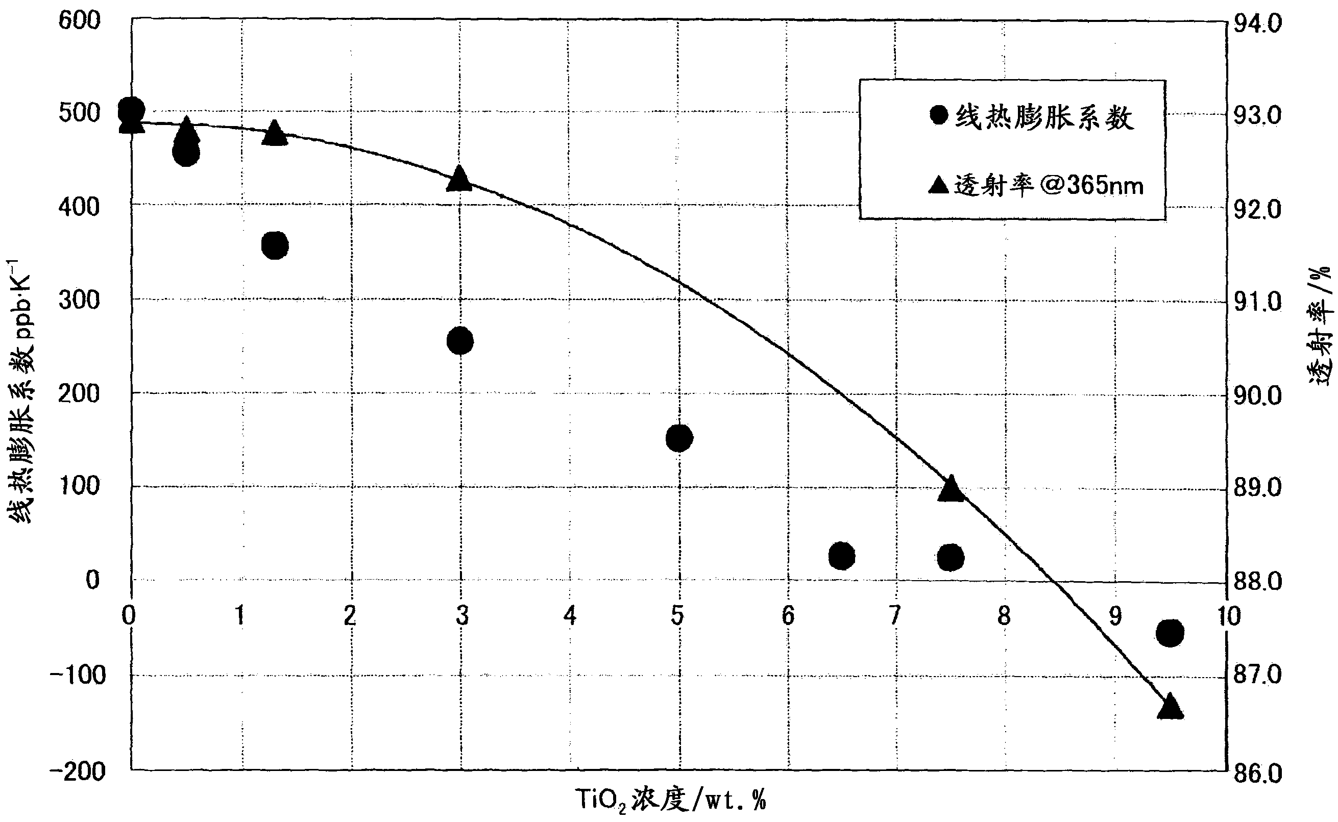
However, in a composition around 7.5% by weight, the transmittance at a wavelength around 365 nm is less than 90%, which cannot be said to be sufficient transmittance.

Method used


Image

  • Optical member for photomask and method for manufacturing the optical member
  • Optical member for photomask and method for manufacturing the optical member
  • Optical member for photomask and method for manufacturing the optical member

Examples


Embodiment approach 1

[0018] Embodiments of the optical member of the present invention will be described. The optical member of this embodiment is made of synthetic quartz glass (SiO 2 ) added 3.0 to 6.5% by weight of TiO 2 The resulting optical member can be in any shape. It is desirable that the optical member does not contain TiO 2 with SiO 2 other substances. For example, even when elements such as Al, Cu, Fe, Na, and K are contained as impurities, it is preferable that, for example, Al is 0.1 wt.ppm or less, Cu is 0.05 wt.ppm or less, and Fe is 0.1 wt.ppm or less, Na is 0.05 wt·ppm or less, and K is 0.05 wt·ppm or less.

[0019] A method for producing the glass material of this embodiment will be described. First, in the synthesis furnace modulated by SiO 2 Particles and TiO 2 A stacked intermediate (soot body) composed of a mixture of particles. The soot body is an aggregate of fine particles, and a method of making the aggregate transparent by heating the aggregate to a glass trans...

Embodiment approach 2

[0030] In this embodiment, the improvement method of the manufacturing method of the optical member for photomasks demonstrated in Embodiment 1 is demonstrated. As mentioned above, by containing TiO 2 When quartz glass with a smaller expansion coefficient is used as an optical member for a photomask, TiO is preferable. 2 Resulting in less internal absorption. When using a material with a lot of internal absorption as an optical member for a photomask, in order to prevent the absorbed exposure light from increasing the temperature of the photomask or from irradiating the wafer due to a decrease in the transmittance of the photomask The reduction of the exposure light requires countermeasures such as increasing the power of the exposure light on the light source side, so it is different from that not containing TiO 2 Compared to quartz glass, it is desirable to increase the internal absorption of the material with as little as possible. The present inventors, as described in ...


PUM

PropertyMeasurementUnit
thicknessaaaaaaaaaa
lengthaaaaaaaaaa
thicknessaaaaaaaaaa

Abstract

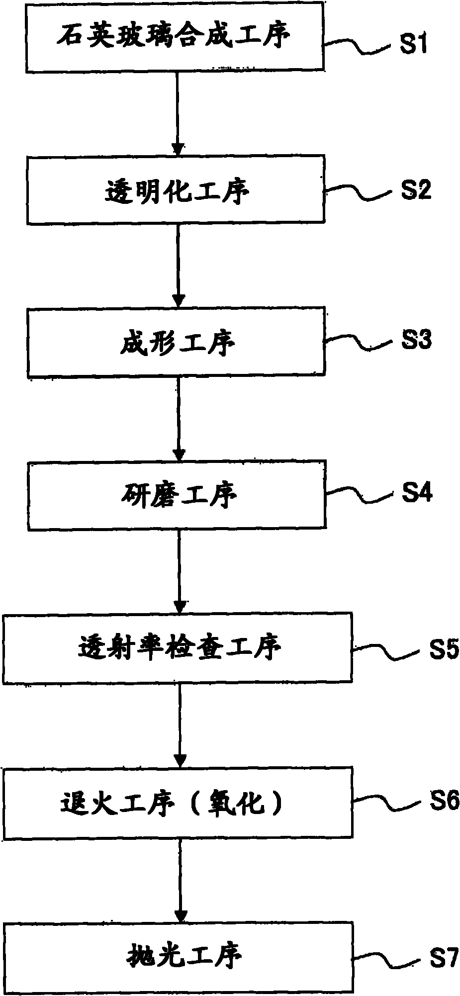
An optical member for a photomask is provided by adding TiO2 to a synthetic quartz glass. The optical member contains 3.0 to 6.5 wt% of TiO2. In a method for manufacturing the optical member, after synthesizing a quartz glass ingot, the ingot is formed in a predetermined flat-board shape and then annealed in oxidizing atmosphere. Light absorption due to Ti3+ can be reduced by changing the Ti3+ inthe quartz glass ingot to Ti4+ by annealing. Since the transmissivity to light having a wavelength of 365 nm is 90% or more, the optical member has sufficient transmissivity for practical use even tolight having a wavelength close to 365 nm, and does not easily expand due to heat compared with quartz glass.

Description

technical field [0001] The present invention relates to a photomask blank used in the manufacture of flat panel displays (hereinafter referred to as FPDs) such as liquid crystal panels, and a method for manufacturing the same. Background technique [0002] The FPD is manufactured through the process of forming elements of the FPD with high precision on the surface of a glass substrate. Photolithographic techniques are used in this process. That is, a photomask of a photomask pattern formed with high precision on the surface of a flat plate-shaped transparent substrate excellent in planarity is illuminated with exposure light, and an image of the photomask pattern is formed on a substrate coated with a photoresist in advance. After being placed on the glass substrate, development is performed to form a photoresist pattern on the surface of the glass substrate. [0003] However, due to the enlargement of the screen size of the FPD and the improvement in production efficiency...

Claims


Application Information

Patent Timeline
Patent Type & Authority Applications(China)
IPC IPC(8): G03F1/14C03C3/06G03F1/00
CPCC03B2201/07G03F1/14C03C2201/30C03B19/1453C03B19/1469C03C2203/40C03C2201/32C03C3/06C03B2201/42C03C2203/54C03C2201/50C03C2203/42C03C2201/42G03F1/50
Inventor 吉成俊雄安住美菜子木村幸泰
Owner NIKON CORP
Learn More