
Method for manufacturing raised grating alignment mark in imprinting lithography

A technology for alignment marks and manufacturing methods, which is applied in microlithography exposure equipment, photoplate making process of pattern surface, optics, etc., can solve the problems of alignment image contrast drop, etc., to achieve improved accuracy, wide application range, and improved Effect of Imprint Alignment Accuracy

Inactive Publication Date: 2011-05-11
XI AN JIAOTONG UNIV
View PDF2 Cites 15 Cited by
  • Summary
  • Abstract
  • Description
  • Claims
  • Application Information

AI Technical Summary

Problems solved by technology

[0007] The purpose of the present invention is to overcome the above-mentioned shortcomings of the prior art, and to provide a method for manufacturing raised grating alignment marks in imprint lithography, which can improve the moiré alignment image caused by the introduction of photoresist The problem of severe decrease in contrast, insensitive to changes in the refractive index of photoresist, suitable for imprint alignment of many common photoresist imprint processes

Method used


Image

  • Method for manufacturing raised grating alignment mark in imprinting lithography
  • Method for manufacturing raised grating alignment mark in imprinting lithography
  • Method for manufacturing raised grating alignment mark in imprinting lithography

Examples


Embodiment Construction

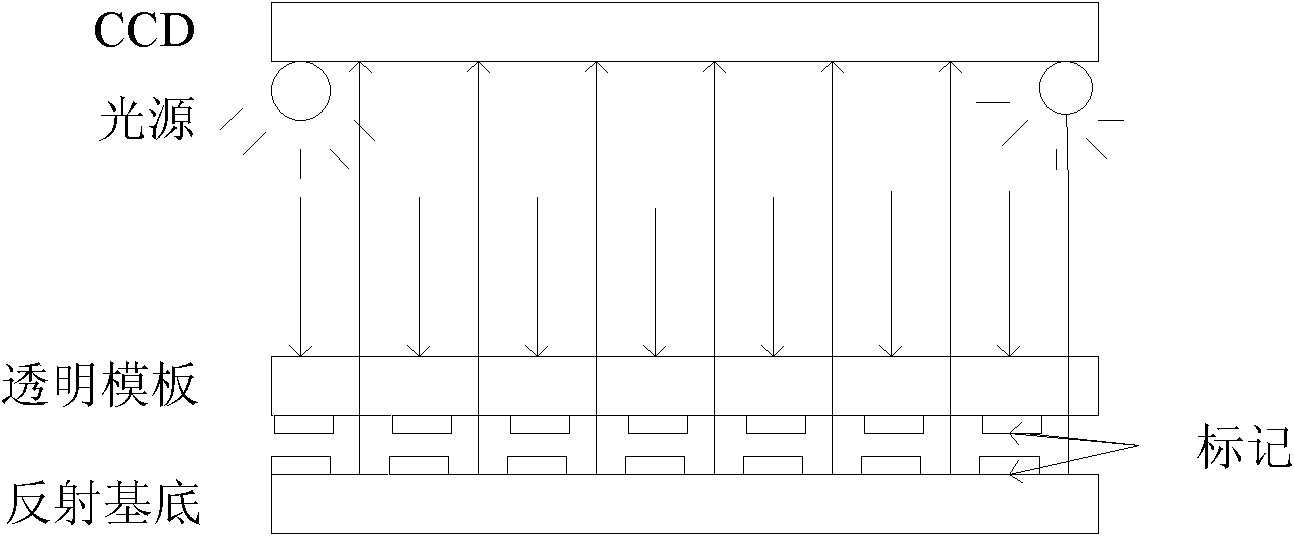
[0042] The manufacturing method of the raised grating alignment mark in the imprint lithography of the present invention specifically comprises the following steps:

[0043] (1) grating material selection:

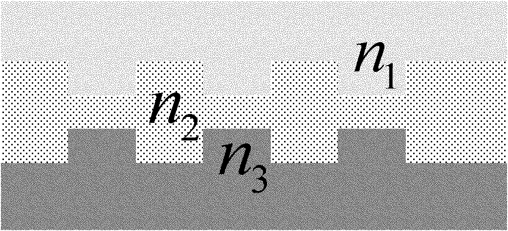
[0044] Based on the imprint lithography alignment of Moiré fringe phase matching, through the Fresnel interface theorem and time-domain finite difference calculation, the relationship between the contrast of the Moiré fringe image and the refractive index of the grating material is analyzed to determine the correspondence between the high-contrast Moiré fringe image The refractive index range of the refraction grating, and select the grating marking material within this range. In imprinting, under the condition that the substrate is Si and the template is glass, the template grating material is a material with a refractive index of about 1.9, and the material used for the substrate is It is a material with a refractive index of about 2.7.

[0045] (2) Raised grating produ...


PUM

PropertyMeasurementUnit
refractive indexaaaaaaaaaa

Abstract

The invention discloses a method for manufacturing a raised grating alignment mark in imprinting lithography, which comprises the following steps of: (1) determining a refractive grating refraction index range for acquiring high-contrast Moire fringe images, and selecting a grating material in the range; (2) photo-etching: manufacturing a grating mark mask plate, and etching a photoresist layer by using the grating mark mask plate as a mask to respectively obtain photoresist grids on an imprinting substrate and a template; (3) sputtering: sputtering on the substrate with photoresist grid lines to optimize the grating material; and (4) peeling off: peeling the photoresist area on the substrate to obtain raised grating fringes. The method optimizes the grating mark manufacturing material by adopting interface optical theory and finite difference computation. The method solves the problem that the Moire fringe alignment image contrast of the traditional mark declines seriously due to the introduction of imprinting photoresist from the aspect of the grating manufacturing material, has wider photoresist application range, and can be applied to introduction of various common photoresists.

Description

technical field [0001] The invention belongs to the technical field of nano-imprint lithography mid-engraving alignment, and relates to a method for manufacturing a grating alignment mark, in particular to a method for manufacturing a raised grating alignment mark that improves the image quality of Moiré fringes, which can improve the The quality of the moiré-aligned image in the case of a resist. Background technique [0002] Imprint lithography is one of the representatives of the next-generation 16nm node lithography technology due to its high resolution, high efficiency and low cost, which can effectively solve the size limitation caused by the pattern diffraction problem of traditional lithography. Although imprint lithography has the advantages of high resolution, high efficiency and low cost in pattern transfer, there are still many key problems to be solved in order to make it a practical and competitive micro-nano manufacturing technology, many of which Layer posit...

Claims


Application Information

Patent Timeline
Patent Type & Authority Applications(China)
IPC IPC(8): G03F9/00G03F7/20
Inventor 王莉丁玉成周洁宗学文魏慧芬卢秉恒
Owner XI AN JIAOTONG UNIV
Learn More