
Cold cathode spot lamp

A technology for cold cathode and cold cathode fluorescent lamps, which is applied to the parts, lighting devices, light sources and other directions of gas discharge lamps, can solve the problems of unfavorable environmental protection, unsuitable indoor and outdoor decoration, difficult and accurate control of mercury content in lamps, etc. To achieve the effect of preventing human injury, reducing eye fatigue, and low maintenance cost

Inactive Publication Date: 2012-10-10
YICHANG JINSEN OPTRONICS TECH
View PDF2 Cites 0 Cited by
  • Summary
  • Abstract
  • Description
  • Claims
  • Application Information

AI Technical Summary

Problems solved by technology

[0003] The use of energy-saving lamps as spotlights has the following disadvantages: 1. Using a rectifier to drive, there is a stroboscopic phenomenon, which will have a great impact on vision, and frequent switching is easy to damage the driving components, short life, and needs to be replaced frequently. It is not suitable for indoors. External decoration; 2. The service life of the lamp tube is short, only about 8000 hours; 3. The color rendering is poor, and the color rendering index is usually difficult to reach 85Ra; 4. The mercury content in the lamp tube is difficult to control accurately, which is not conducive to environmental protection; 5. , Relatively high energy consumption, wasting energy
[0004] The use of incandescent lamps as spotlights has the following disadvantages: 1. The service life of the bulb is short, only about 1000-2000 hours; 2. The light efficiency is low, only 10-15Lm / W, energy consumption; 3. The service life is short and needs to be replaced frequently Increase the cost of use

Method used


Image

  • Cold cathode spot lamp
  • Cold cathode spot lamp
  • Cold cathode spot lamp

Examples


Embodiment Construction

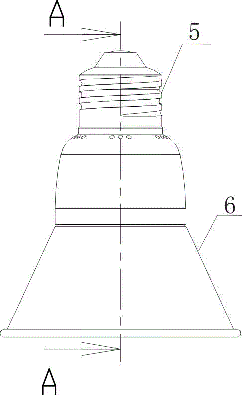
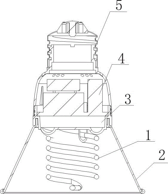
[0028] Such as figure 1 , figure 2 with image 3 As shown, the present invention includes a lamp holder 5 , an inverter 4 is installed inside the lamp holder 5 , the lower end of the lamp holder 5 is engaged with a CCFL assembly 6 , and the CCFL assembly 6 is connected to the inverter 4 .

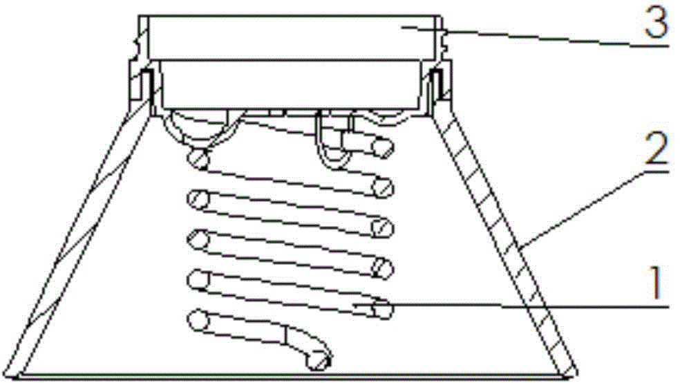
[0029] In the cold cathode fluorescent lamp assembly 6, the upper end of the plastic part 3 is fastened with the lamp holder 5, the cold cathode fluorescent lamp tube 1 and the spotlight cup 2 outside the cold cathode fluorescent lamp tube 1 are installed at the lower end of the plastic part 3, and the cold cathode fluorescent lamp tube 1 The electrodes are connected to the output terminals of the inverter 4 .

[0030] The lower end of the plastic part 3 is provided with a threaded groove, which is used to limit the position of the lamp tube 1 and the spotlight cup 2. The contact parts are glued with soft silicone in an appropriate way to form a whole; the silicone will wrap the lamp tu...


PUM


Abstract

The invention relates to a cold cathode spot lamp, comprising a lamp holder. The lamp holder is internally provided with an inverter; the lower end of the lamp holder is fastened with a cold cathode fluorescent lamp component which is connected with the inverter; in the cold cathode fluorescent lamp component, the upper end of a plastic piece is fastened with the lamp holder; a cold cathode fluorescent lamp tube and a spot lamp cup outside the cold cathode fluorescent lamp tube are arranged at the lower end of the plastic piece; and an electrode of the cold cathode arc fluorescent lamp tube is connected with the output end of the inverter. By utilizing the cold cathode spot lamp, the defects of the existing energy-saving lamp or filament lamp can be defected, the provided light is stable,the color rendering property is good, the stroboflash and flicker phenomena are avoided, the vision can be effectively protected, the service life is long, the energy is saved, the environment is protected, the maintenance is simple, and the energy consumption is low.

Description

technical field [0001] The invention relates to a lighting fixture, in particular to a cold cathode spotlight. Background technique [0002] Existing indoor and outdoor decorative spotlights usually adopt energy-saving lamps (neon tube lamps) or incandescent lamps, which have disadvantages. [0003] The use of energy-saving lamps as spotlights has the following disadvantages: 1. Using a rectifier to drive, there is a stroboscopic phenomenon, which will have a great impact on vision, and frequent switching is easy to damage the driving components, short life, and needs to be replaced frequently. It is not suitable for indoors. External decoration; 2. The service life of the lamp tube is short, only about 8000 hours; 3. The color rendering is poor, and the color rendering index is usually difficult to reach 85Ra; 4. The mercury content in the lamp tube is difficult to control accurately, which is not conducive to environmental protection; 5. , Relatively high energy consumpti...

Claims


Application Information

Patent Timeline
IPC IPC(8): H01J61/36H01J61/32H05B41/36
Inventor 李超覃超
Owner YICHANG JINSEN OPTRONICS TECH
Learn More