


Quick Research
Generate reliable direction feasibility study reports for your R&D in just a few steps.

Technical Q&A
Discover and master advanced knowledge NOW. Basics, ideas, possibilities, all at once.

Find Solutions
As an expert in R&D theories, this can generate solutions to your technical problems instantly.

Evaluate Feasibility
Analyze your overall solution with one click, know your potential R&D risks in advance.

Monitor Landscape
Get weekly tech updates, stay abreast of the latest tech innovations and key insights.
Fuel cell and method for diassembling the same
A technology for fuel cells and cell stacks, which is applied in the fields of fuel cells, fuel cell disposal/recycling, fuel cell grouping, etc. safety effect
- Summary
- Abstract
- Description
- Claims
- Application Information
AI Technical Summary
Problems solved by technology
Method used
Image

Examples
no. 1 Embodiment approach
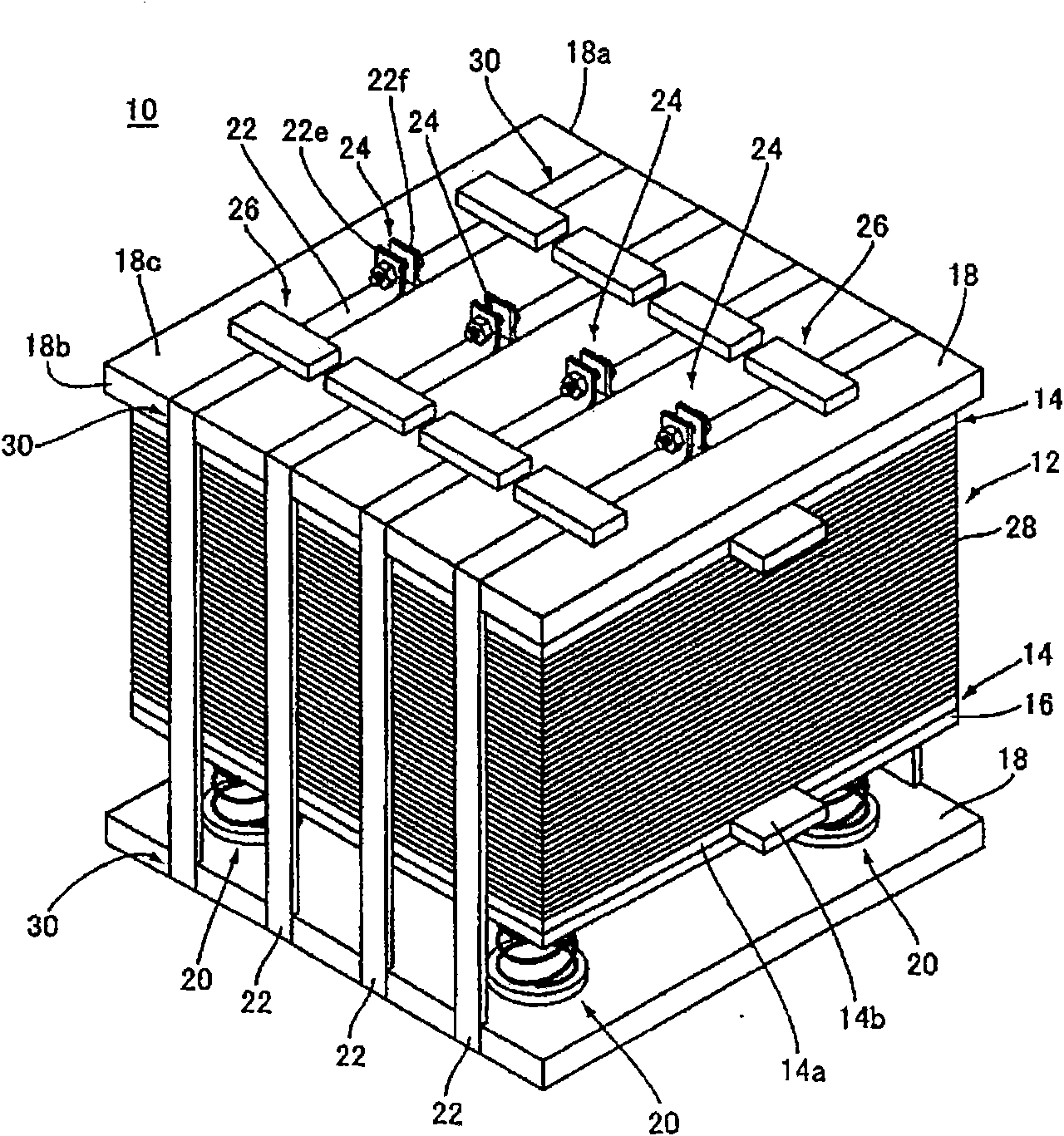
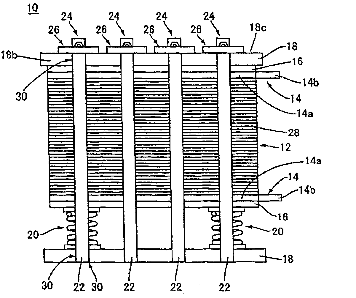
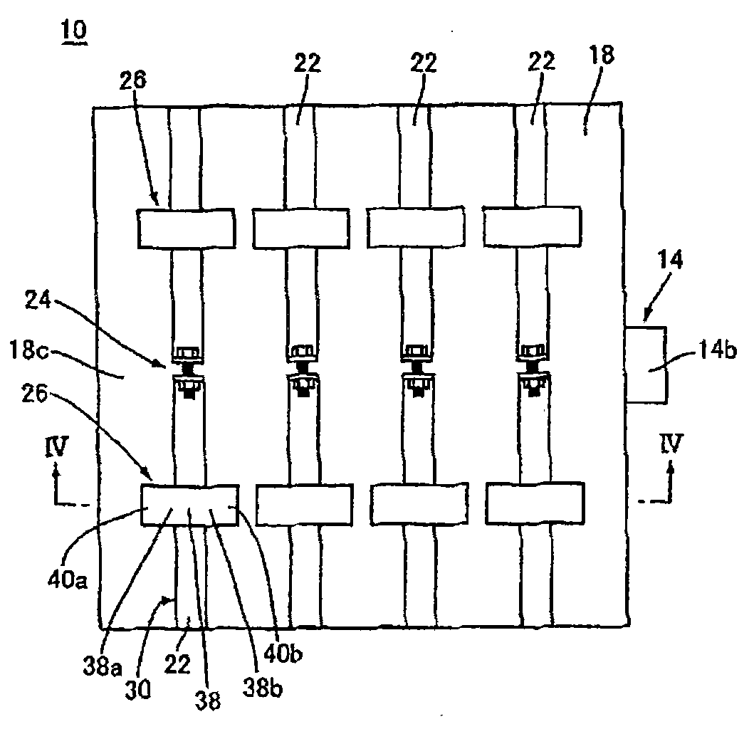
[0075] figure 1 is a perspective view showing the structure of the fuel cell 10 according to the first embodiment of the present invention, figure 2 is a front view showing the structure of the fuel cell 10, image 3 It is a plan view showing the structure of the fuel cell 10 . in addition, Figure 4 yes image 3 Partial sectional view of line IV-IV in, Figure 5 yes Figure 4 Enlarged part of the figure.
[0076] Fuel Cell 10( Figure 1~3 ) is a solid polymer fuel cell (PEFC) used in household cogeneration systems, two-wheeled vehicles, electric vehicles or hybrid electric vehicles, such as figure 1 as well as figure 2 As shown, a battery stack 12, a current collector plate 14 arranged on both sides in the stacking direction of the battery stack 12, an insulating plate 16, and an end plate 18 are provided. The compression spring 20 between the plate 16 and the end plate 18, a plurality of (four in this embodiment) fastening straps 22 for fastening these components,...
no. 2 Embodiment approach
[0098] Figure 8 (A) and (B) are a perspective view and a cross-sectional view showing main parts of a fuel cell 60 according to a second embodiment of the present invention, respectively. The fuel cell 60 is the fuel cell 10 ( figure 1 ) of the displacement limiting part 26 is changed to another displacement limiting part 62 of the fuel cell, and the other structures are the same as those of the fuel cell 10.
[0099] The displacement restricting portion 62 is integrally provided with the end plate 18 on the side where the connecting portion 24 is located, and restricts the displacement of the fastening band 22 in a direction away from the surface 18c of the end plate 18, and has a connection with the fastening band 22. At least a part of the surface 22d faces a planar facing surface 64c, and has a plate-shaped facing portion 64 disposed so as to intersect (in this case, be perpendicular to) the recessed portion 30 , and a plate-shaped facing portion 64 connected in a direct...
no. 3 Embodiment approach
[0110] Figure 11 (A) and (B) are a perspective view and a cross-sectional view showing main parts of a fuel cell 90 according to a third embodiment of the present invention, respectively. The fuel cell 90 is the fuel cell 10 ( figure 1 ) is changed to a fuel cell in which the displacement restricting part 26 is another displacement restricting part 92, and the other structures are the same as those of the fuel cell 10.
[0111] The displacement restricting portion 92 has screw holes 94 provided on both sides of the recess 30 on the surface 18 c sandwiching the end plate 18 and two through holes 96 a corresponding to the screw holes 94 , and has a surface compatible with the fastening band 22 . At least a part of 22d faces a plate-shaped opposing member 96 and two screws 98 that are inserted through the through-hole 96a and screwed into the threaded hole 94 .
[0112] According to the third embodiment, after the fastening band 22 is housed in the concave portion 30, the oppo...
PUM
 Abstract
Description
Claims
Application Information
 - R&D Engineer
- R&D Manager
- IP Professional
- Industry Leading Data Capabilities
- Powerful AI technology
- Patent DNA Extraction
Browse by: Latest US Patents, China's latest patents, Technical Efficacy Thesaurus, Application Domain, Technology Topic, Popular Technical Reports.
© 2024 PatSnap. All rights reserved.Legal|Privacy policy|Modern Slavery Act Transparency Statement|Sitemap|About US| Contact US: help@patsnap.com