
Vibration suppression device

A vibration suppression and chattering technology, applied in the direction of manufacturing tools, maintenance and safety accessories, measuring/indicating equipment, etc., can solve the problems of poor time efficiency and achieve the effect of preventing damage and suppressing chattering

Inactive Publication Date: 2011-04-27
OKUMA CORP
View PDF15 Cites 32 Cited by
  • Summary
  • Abstract
  • Description
  • Claims
  • Application Information

AI Technical Summary

Problems solved by technology

Therefore, in the structure in which the operator manually changes the rotational speed to the rotational speed displayed on the display device, the operator must change the rotational speed several times until it finally reaches a stable state, which has a problem of very poor time efficiency.

Method used


Image

  • Vibration suppression device
  • Vibration suppression device
  • Vibration suppression device

Examples


Embodiment Construction

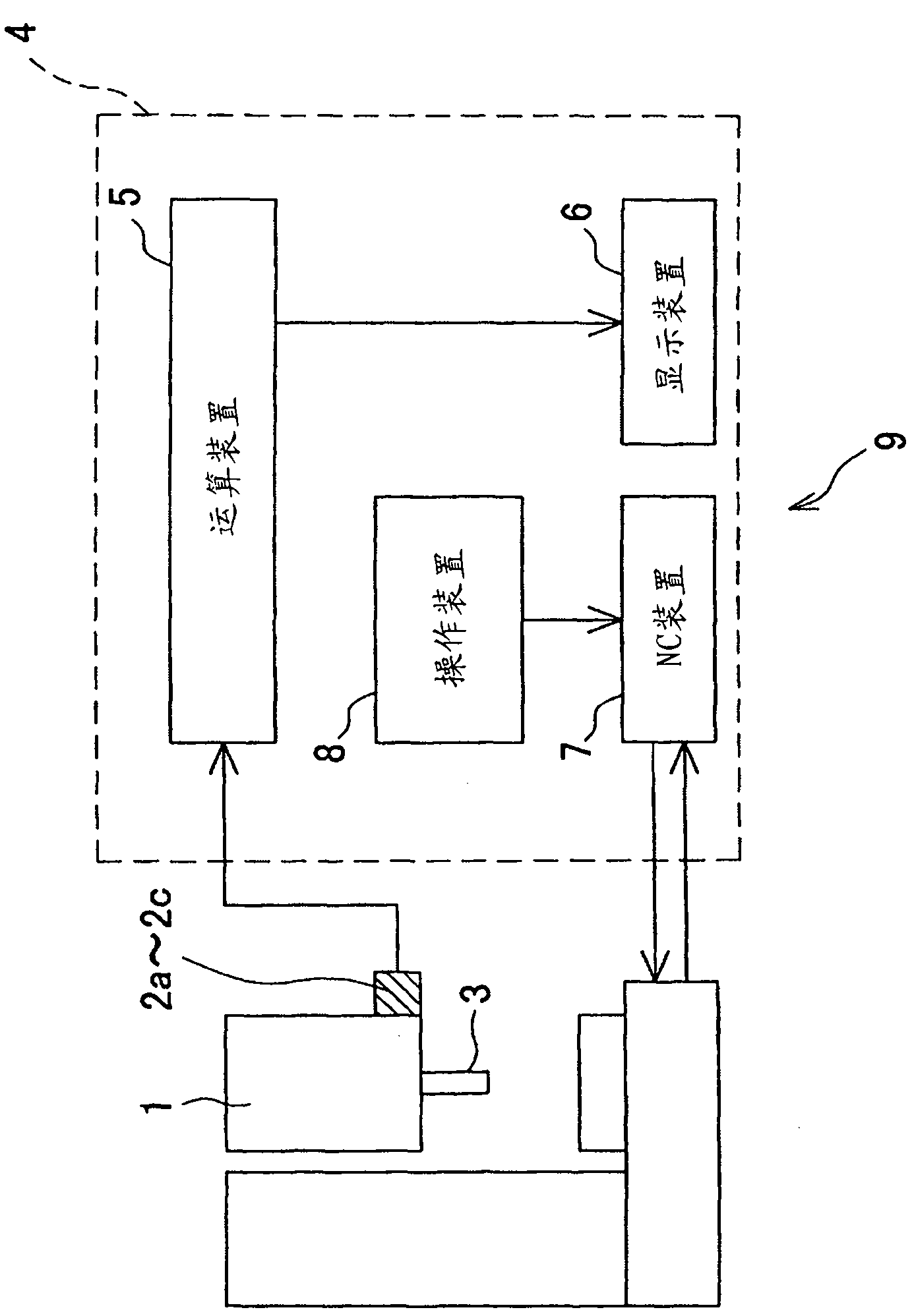
[0037] Hereinafter, a vibration suppressing device as an embodiment of the present invention will be described in detail with reference to the drawings.

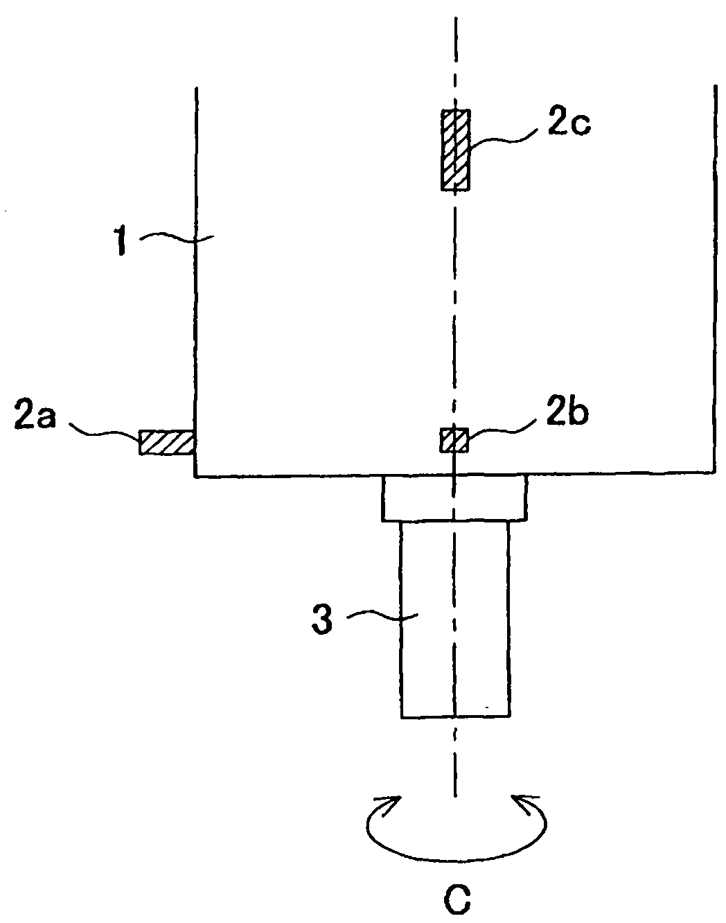
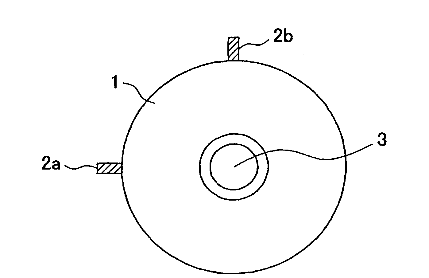
[0038] The vibration suppressing device 9 is a device for suppressing "chatter" generated on the rotating shaft 3, which is provided in the rotating shaft housing 1 in a manner to be rotatable around the C axis, and is used for detecting Vibration sensors 2a to 2c for vibration acceleration generated by the rotating shaft 3 and a control device 4 for controlling the rotational speed of the rotating shaft 3 based on detection values ​​detected by the vibration sensors 2a to 2c are configured.

[0039] Such as figure 2 and image 3 As shown, the vibration sensors 2a to 2c are mounted on the rotating shaft housing 1, and one vibration sensor detects vibration acceleration in a direction perpendicular to the other two vibration sensors. Therefore, the vibration accelerations in the X-axis, Y-axis, and Z-axis directions orthog...


PUM


Abstract

The invention provides a vibration suppression device, which can reliably and quickly suppress the flutter and realize the precision increase of processing surfaces, long service life of tools and high efficiency of processing.Vibration acceleration detected by vibration sensors (2a - 2c) is momentarily analyzed and the operation based on the analyzed result is carried out by an arithmetic unit (5).The analyzed result and the operation result are displayed on a display unit (6) in real time.When "flutter" is suppressed, operators can operate an operating means (8) while referring to the display unit (6) to change the rotation speed.Compared with the prior art, wherein the rotation speed is changed based on experiences of operators, the device can suppress "flutter" more accurately and more quickly.

Description

technical field [0001] The present invention relates to a vibration suppression device for suppressing chatter vibration generated during processing in a machine tool that performs processing while rotating a tool or a workpiece. Background technique [0002] Conventionally, for example, there is a machine tool in which a tool is supported on a rotating shaft, and the tool and / or the workpiece are moved relative to each other while being fed, so that the workpiece is processed by the rotating tool. In this machine tool, the so-called "chatter" occurs during machining due to excessive cutting amount, etc., resulting in the deterioration of the machining accuracy of the machined surface and rapid wear or chipping of tools. Therefore, when such "chattering" occurs, the current situation generally employs a method in which the operator empirically changes the rotation speed of the rotating shaft to suppress the "chattering". In addition, as disclosed in Patent Document 1, for e...

Claims


Application Information

Patent Timeline
Patent Type & Authority Applications(China)
IPC IPC(8): B23Q11/00B23Q5/58B23Q17/12
CPCB23Q11/0032B23Q11/0039Y10T409/30084
Inventor 浜口显秀稻垣浩吉野清安藤知治上野浩
Owner OKUMA CORP
Learn More