
Liquid crystal display panel

A liquid crystal display panel and pixel technology, applied in static indicators, nonlinear optics, instruments, etc., can solve the problems of short maximum effective charging time, large RC delay, poor display effect of liquid crystal display panels, etc., and achieve a balance between cost and display The effect of quality, long actuation times

Inactive Publication Date: 2011-04-20
TCL CHINA STAR OPTOELECTRONICS TECH CO LTD
View PDF1 Cites 4 Cited by
  • Summary
  • Abstract
  • Description
  • Claims
  • Application Information

AI Technical Summary

Problems solved by technology

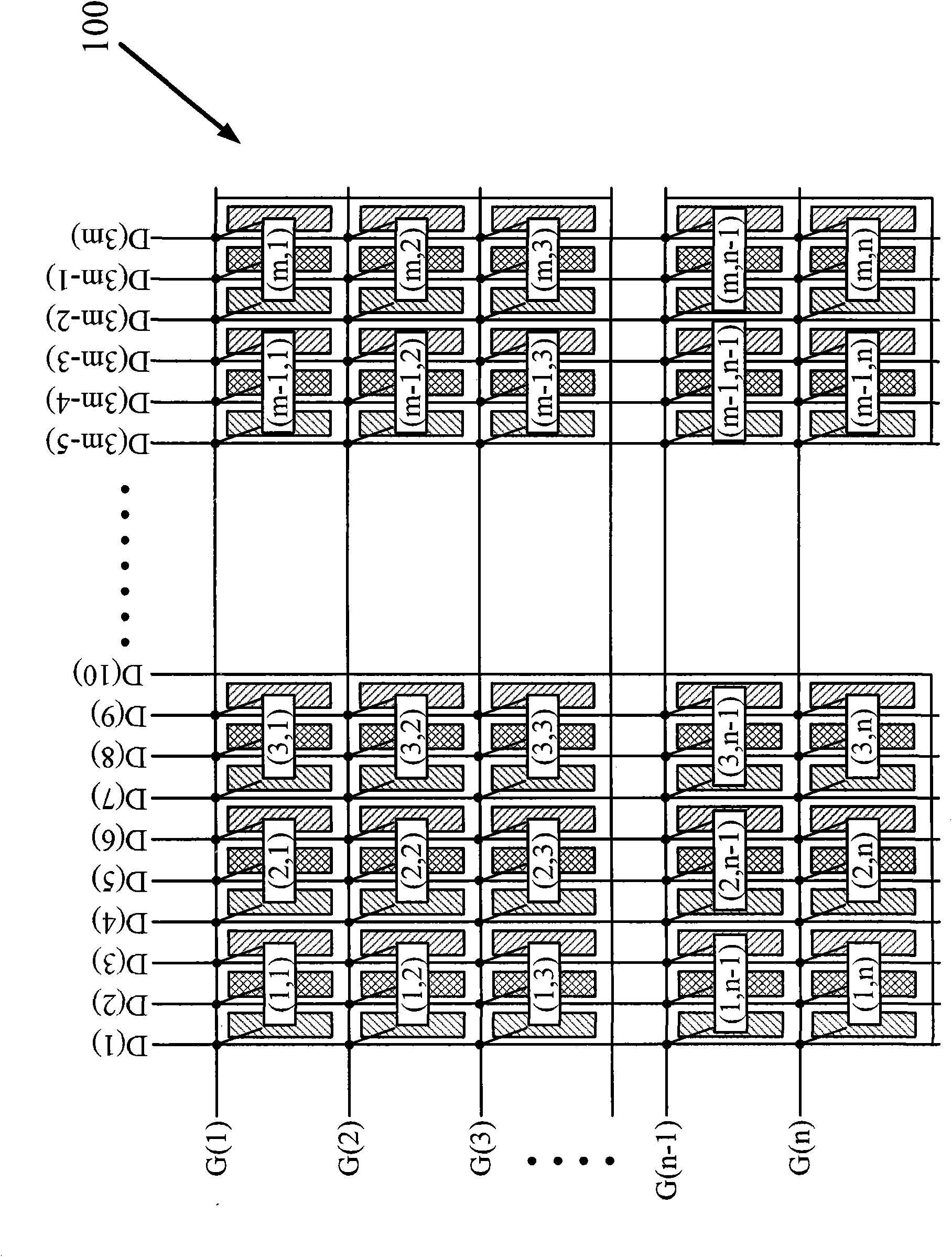
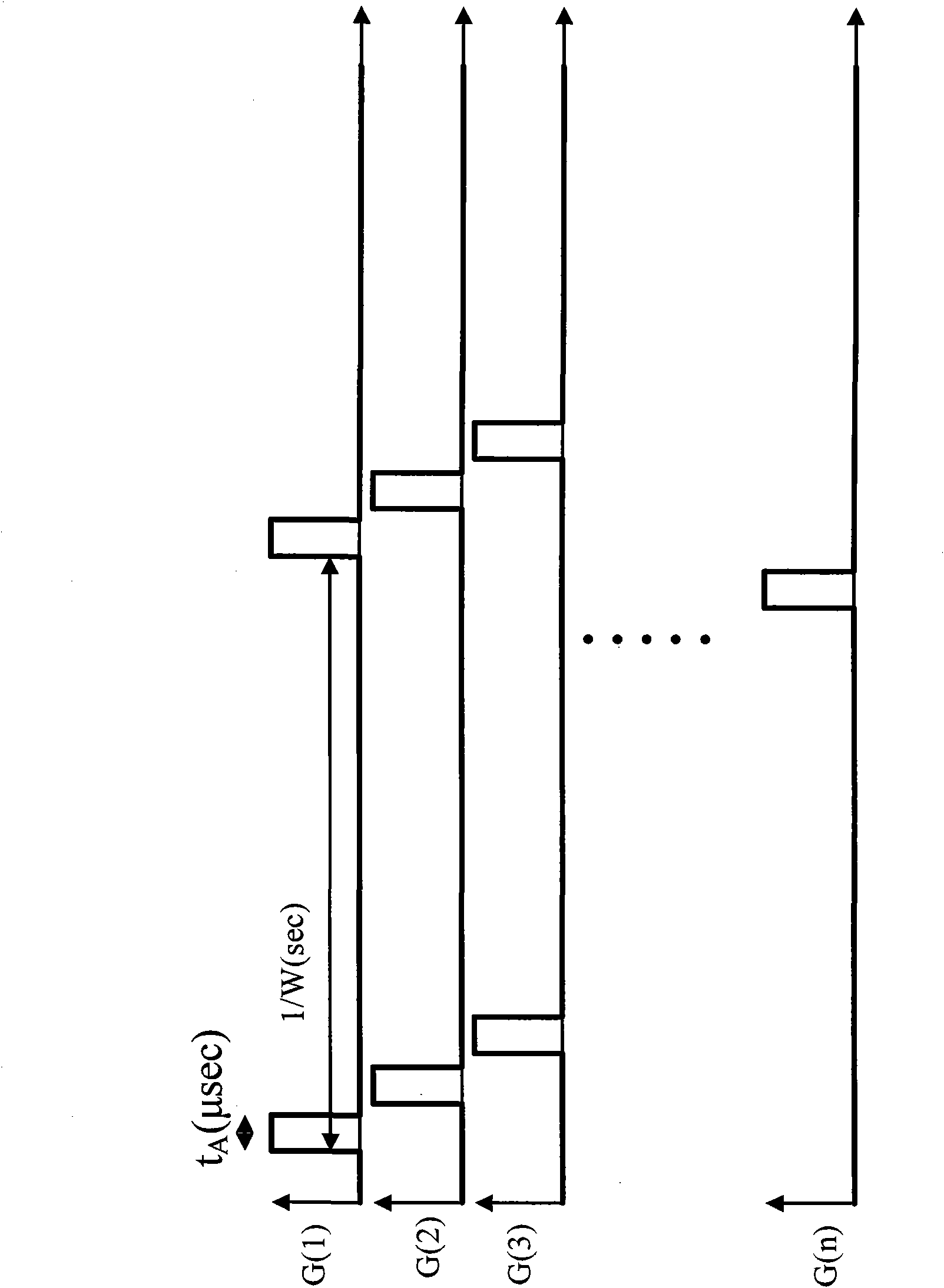
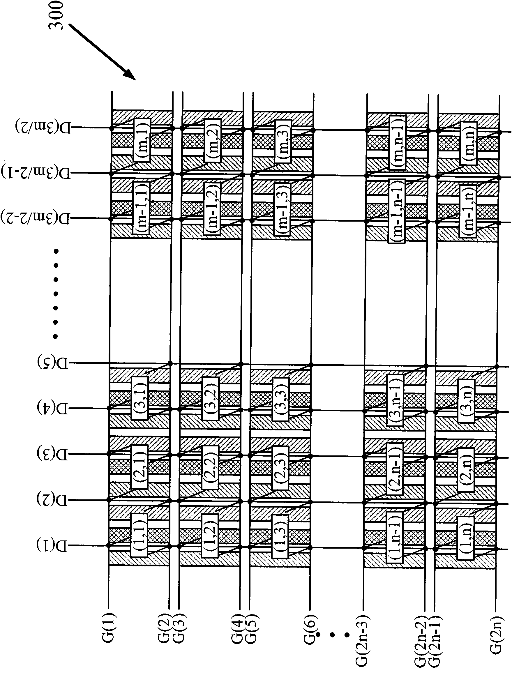
However, such an approach will have a large RC delay (RC delay) because the number of scan lines crossed by the data line is large, and because the maximum effective charging time of the latter two approaches is relatively short (compare t A , t B , t C ), therefore, it may be difficult for the sub-pixels to be charged to the correct potential, resulting in poor display effects of the liquid crystal display panels 300 and 500

Method used


Image

  • Liquid crystal display panel
  • Liquid crystal display panel
  • Liquid crystal display panel

Examples


Embodiment Construction

[0025] The following descriptions of the various embodiments refer to the accompanying drawings to illustrate specific embodiments in which the present invention can be practiced. The directional terms mentioned in the present invention, such as "up", "down", "front", "back", "left", "right", "top", "bottom", "horizontal", "vertical", etc. , are for orientation only with reference to the attached drawings. Therefore, the directional terms used are used to illustrate and understand the present invention, but not to limit the present invention.

[0026] see Figure 7 , Figure 7 It is a schematic diagram of a liquid crystal display panel 700 according to an embodiment of the present invention. Such as Figure 7 As shown, the resolution of the liquid crystal display panel 700 is m×n, where n is a multiple of 2. In addition, in this embodiment, the RGB three sub-pixels (sub-pixel) of one pixel are arranged in the vertical direction, therefore, the actual sub-pixel resolution ...


PUM


Abstract

The invention discloses a liquid crystal display panel comprising m lines and n rows of sub-pixels, wherein n is the multiple of 2. The liquid crystal display panel comprises n / 2 scanning lines and 2m data lines, wherein each scanning line controls two adjacent rows of sub-pixels, and every two data lines control one line of sub-pixels. When the first scanning line starts the first line and the second line of sub-pixels, 2m data lines simultaneously output data to the first row and the second row of sub-pixels. Because RGB three sub-pixels which form one pixel in the liquid crystal display panel are positioned on the same line, the number of source electrode drivers can be reduced to lower cost. In addition, because the liquid crystal display panel drives the sub-pixels in the same line by two data lines, the driving time of the invention is prolonged so as to improve display quality.

Description

technical field [0001] The invention relates to a liquid crystal display panel, in particular to a liquid crystal display panel which can balance cost and display quality. Background technique [0002] Displays with advanced functions have gradually become an important feature of today's consumer electronics products. Liquid crystal displays have gradually become widely used in various electronic devices such as mobile phones, personal digital assistants (PDAs), digital cameras, computer screens or notebook computer screens with high resolution. rate color screen monitor. [0003] see here figure 1 . figure 1 is a schematic diagram of a liquid crystal display panel 100 in the prior art. Such as figure 1 As shown, when the overall resolution of the liquid crystal display panel 100 is m×n, if the RGB three sub-pixels (sub-pixel) of one pixel are arranged in a left-right manner, the actual sub-pixel resolution of the liquid crystal display panel 100 is 3m×n. In addition, t...

Claims


Application Information

Patent Timeline
Patent Type & Authority Applications(China)
IPC IPC(8): G02F1/1362G02F1/133
CPCG02F1/136286G09G3/36G09G2310/0205G09G2310/0218G09G2310/0243
Inventor 陈政鸿贺成明
Owner TCL CHINA STAR OPTOELECTRONICS TECH CO LTD
Learn More