Hybrid power unit control system

A hybrid power and control system technology, applied in the direction of power devices, hybrid vehicles, pneumatic power devices, etc., can solve the problems of increased weight and increased manufacturing costs

Inactive Publication Date: 2011-04-06
AISIN AI CO LTD +2
View PDF6 Cites 16 Cited by
  • Summary
  • Abstract
  • Description
  • Claims
  • Application Information

AI Technical Summary

Problems solved by technology

[0004] In the above vehicle hybrid device, when torsional vibrations are generated in the drive force transmission shaft system due to changes in the torque of the engine, there may be cases where the power transmission gear rattles or rattles the power transmission gear due to an excessive change in the rotational speed of the engine. Noise such as cavity noise of the car body
In the past, mass dampers were installed in rotating parts such as clutches in order to suppress the occurrence of the above-mentioned torsional vibrations, but this led to problems of increased weight and increased manufacturing costs

Method used


Image

  • Hybrid power unit control system
  • Hybrid power unit control system
  • Hybrid power unit control system

Examples


Embodiment Construction

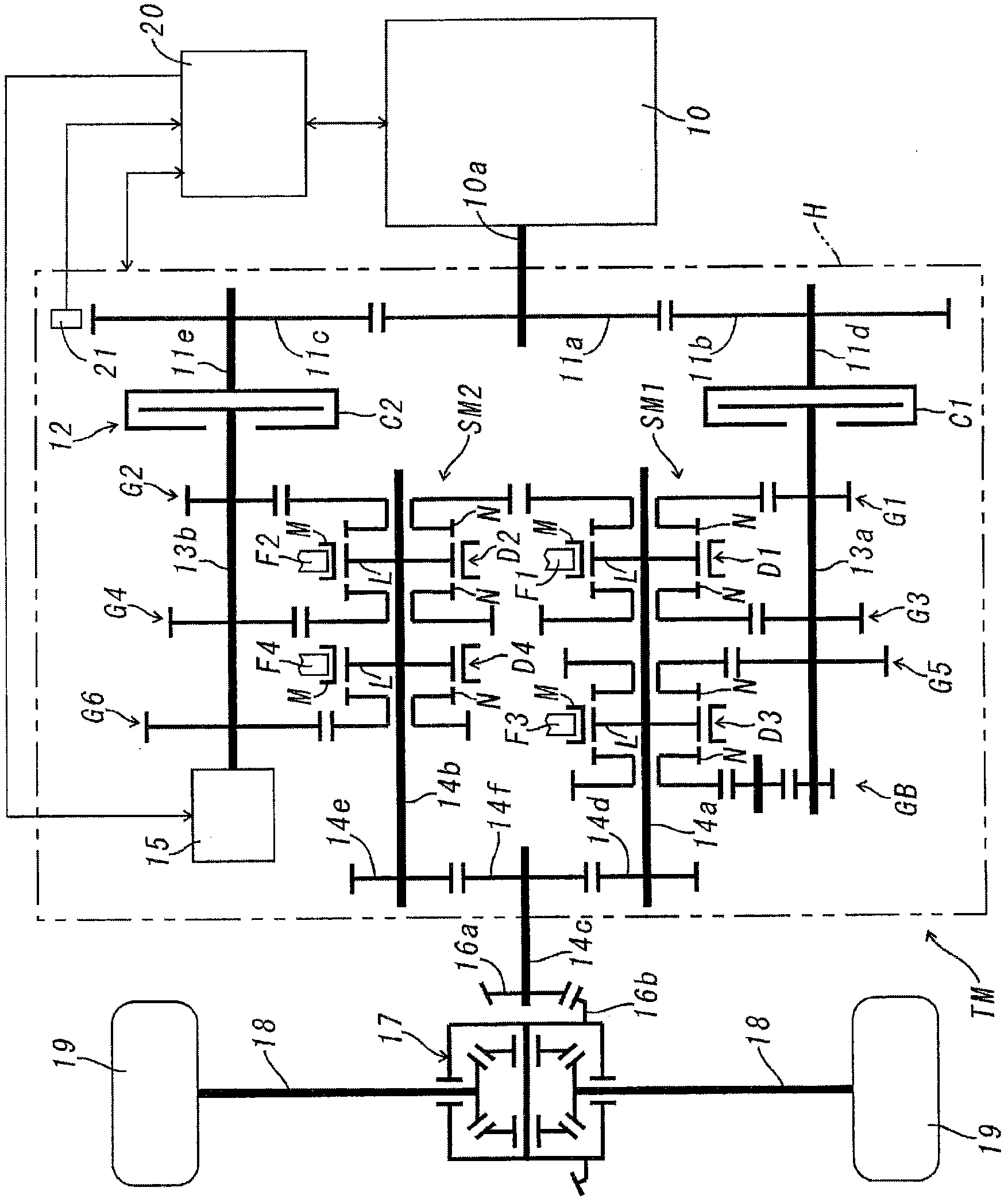
[0018] Below, refer to Figure 1-Figure 4 , the first embodiment of the control system of the hybrid power device of the present invention will be described. In this first embodiment, the hybrid power plant having the control system of the present invention is applied to figure 1 Shown is an automatic transmission TM with 6 forward speeds and 1 reverse speed.

[0019] This automatic transmission TM is a dual-clutch type. In the transmission case H, the first input shaft 13a and the second input shaft 13b, which are arranged in parallel to each other, are supported and can rotate freely, via the first friction clutch C1 and the second friction clutch C2, It is connected to the output shaft 10 a of the engine 10 . The input member of the first friction clutch C1 is coupled to the support shaft 11d of the driven gear 11b, and the drive gear 11a that rotates integrally with the output shaft 10a of the engine 10 meshes with the driven gear 11b. Similarly, the input member of th...


PUM


Abstract

Disclosed is a means to attenuate torsional vibration in a power unit transmission system generated by torque fluctuations in the engine in an automotive hybrid power unit, and thereby eliminate noise, such as chattering from the power transmission gears and muffled body noise, etc. Disclosed is a hybrid power unit control system for a hybrid power unit that is equipped with a first drive train, which is configured with a gear transmission mechanism linked to a first input shaft that transmits engine drive power via a first friction clutch; a second drive train, which is configured with a gear transmission mechanism linked to a second input shaft that transmits engine drive power via a second friction clutch; a motor generator, which is connected to said first input shaft or second input shaft; and a driven apparatus, which is driven by the drive power transmitted from the output shaft of the gear transmission mechanism of said first drive train or the output shaft of the gear transmission mechanism of said second drive train. Said motor generator is started as an electric power generator when fluctuation in the rotational speed of said engine, which is detected by a rotational speed sensor, exceeds a predetermined upper limit amplitude value, so that torque of opposite phase to said rotational speed fluctuation is applied to said engine with the same periodicity as said rotational speed fluctuation.

Description

technical field [0001] The present invention relates to a hybrid power device suitable for a transmission of a hybrid vehicle, in particular to a control system for a hybrid power device suitable for a dual-clutch transmission. Background technique [0002] Japanese Patent Application Laid-Open No. 2005-186931 discloses a hybrid device employing such a dual clutch. The hybrid device has a first input shaft and a second input shaft which are coaxially arranged and can rotate relative to each other and selectively transmit the driving force of the engine through a dual clutch, and are respectively installed on the first output shaft arranged in parallel with the two input shafts. The first gear transmission mechanism and the second gear transmission mechanism on the shaft and the second output shaft, and the driving wheel connected to the second output shaft and connected to the second output shaft as an electric motor to drive the first output shaft or the second output shaft...

Claims


Application Information

Patent Timeline
Patent Type & Authority Applications(China)
IPC IPC(8): B60W10/08B60K6/36B60K6/387B60K6/48B60K6/547B60L11/14B60W10/06B60W20/00B60L50/16
CPCB60W2510/0638B60W10/113B60K6/48F16H3/093Y02T10/6286B60L2200/26B60L2240/441B60W10/08Y02T10/642B60K6/547B60W20/00B60W10/06B60L2240/423B60W2710/083B60L11/14F16H2200/0052F16H3/006B60K6/36Y02T10/7077B60Y2400/428Y02T10/6221B60W30/20B60L50/16Y10T74/19014Y02T10/62Y02T10/64Y02T10/7072B60W20/40B60W20/30B60W10/02Y02T10/70
Inventor 丹波俊夫福原裕一佐佐木环村上香治大村雅洋
Owner AISIN AI CO LTD
Why Eureka
Try Eureka