
Torsional Percussion Drilling Speed ​​Up Tool

A technology of percussion drilling and tools, applied in percussion drilling, drilling equipment, driving devices for drilling in boreholes, etc., can solve the problems of size deviation of moving parts, high drilling cost, low rock breaking efficiency, etc., and achieve greater Cutting load, improving rock-breaking efficiency, and improving rock-breaking efficiency

Active Publication Date: 2019-06-25
BEIJING UNIV OF TECH +1
View PDF5 Cites 0 Cited by
  • Summary
  • Abstract
  • Description
  • Claims
  • Application Information

AI Technical Summary

Problems solved by technology

[0006] The above-mentioned problems are mainly caused by the internal structure of the tool. Most of the current torsion impactors use the "surface-to-surface" contact friction method, especially at the position where the load is received, which will make the The service life is severely reduced. Once the wear reaches a certain level, the corresponding channel will leak, the size of the moving parts will deviate, etc., which will cause the tool to fail early, resulting in low rock breaking efficiency and high drilling costs.

Method used


Image

  • Torsional Percussion Drilling Speed ​​Up Tool
  • Torsional Percussion Drilling Speed ​​Up Tool
  • Torsional Percussion Drilling Speed ​​Up Tool

Examples


Embodiment Construction

[0044] In order to have a clearer understanding of the technical features, purposes and effects of the present invention, the specific implementation manners of the present invention will now be described with reference to the accompanying drawings.

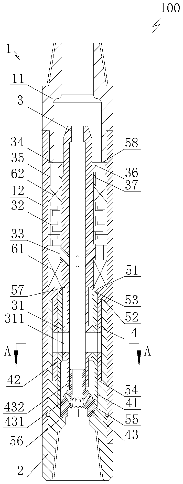
[0045] Such as Figure 1 to Figure 7 As shown, the present invention provides a torsional percussion drilling speed-increasing tool 100, comprising a shell body 1 ( figure 1 It is a schematic diagram of the normal working state of the torsional percussion drilling speed increasing tool 100, figure 1 The top of the middle shell body 1 is connected to the drill collar), the shell body 1 is provided with a shell center hole penetrating in the axial direction, and the other end of the shell body 1 is provided with a drill seat coaxially fixedly sleeved in the shell center hole from outside to inside 2. The drill seat 2 is provided with a drill seat center hole arranged axially through, and the end of the drill seat center hole away ...


PUM


Abstract

The invention is a torsional impact drilling acceleration tool. The torsional impact drilling acceleration tool includes a shell body, the shell body is internally provided with a shell center hole, adrill bit seat is arranged at the other end of the shell boy, the drill bit seat is internally provided with a drill bit seat center hole, and a drill bit can be sleeved with the end, away from the shell body, of the drill bit seat center hole in a sealing mode. A driving shaft is coaxially sleeved with the shell center hole, the driving shaft is internally provided with a driving shaft center hole which is formed in the axial direction in a penetrating mode, and one end of the driving shaft is arranged in the drill bit seat center hole in a penetrating mode. A circumferential impact structure is arranged on the outer wall of one end of the driving shaft in a sleeving mode, the circumferential impact structure can produce circumferential reciprocating impact and is fixed in the axial direction, the circumferential impact structure is internally provided with a circumferential impact structure center hole which is formed in the axial direction in a penetrating mode, and the circumferential impact structure center hole and the driving shaft center hole can be formed in a communicating mode. The torsional impact drilling acceleration tool is simple in structure and long in service life, the cutting state of the drill bit can be improved, the service life of the drill bit is prolonged, and the efficiency of breaking rock by the drill bit is improved.

Description

technical field [0001] The invention relates to downhole drilling tools in the field of petroleum development, in particular to a tool for increasing the speed of drilling with torsional impact. Background technique [0002] In drilling engineering, the improvement of ROP is an eternal goal. With the development of petroleum exploration and development, the proportion of deep wells and ultra-deep wells is gradually increasing. However, in the drilling process of deep wells and ultra-deep wells, problems such as low mechanical penetration rate and low service life of drill bits are prone to occur, and these problems have greatly increased drilling costs. [0003] During the drilling process of deep wells and ultra-deep wells, the difficulty lies in the high hardness of the rocks, which requires a lot of energy for breaking them. Among the common drilling methods at present, mechanical rock breaking is mostly used, that is, a drill bit is used to cut and break rocks. [000...

Claims


Application Information

Patent Timeline
Patent Type & Authority Patents(China)
IPC IPC(8): E21B4/00E21B4/02E21B1/00
CPCE21B1/00E21B4/00E21B4/02
Inventor 查春青柳贡慧李军
Owner BEIJING UNIV OF TECH
Learn More