Duplex clutches and clutch devices

A clutch and duplex technology, applied in clutches, friction clutches, mechanical drive clutches, etc., can solve the problems of huge, unreliable measurement data, complex structure of duplex clutches, etc., and achieve the effect of compact encoder part and reduced installation space requirements.

Active Publication Date: 2022-03-29
SCHAEFFLER TECH AG & CO KG
View PDF17 Cites 0 Cited by
  • Summary
  • Abstract
  • Description
  • Claims
  • Application Information

AI Technical Summary

Problems solved by technology

[0003] In the designs known from the prior art, it has been found that the dual clutches implemented are either relatively complex and bulky, or that, when the encoder part is arranged on the side of the dual mass flywheel outside the dual clutch, this leads to generation of unreliable measurement data

Method used


Image

  • Duplex clutches and clutch devices
  • Duplex clutches and clutch devices
  • Duplex clutches and clutch devices

Examples


Embodiment Construction

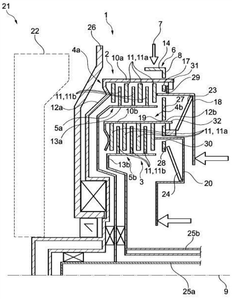
[0031] exist figure 1 In the diagram, the basic structure of the multiple clutch 1 according to the invention can be seen particularly clearly initially. In the exemplary embodiment, the multiple clutch 1 is realized as a double clutch; according to other embodiments, it is also designed as a triple clutch. The multiple clutch 1 has a first clutch 2 and a second clutch 3 . Viewed along the torque transfer path achieved during operation, the two clutches 2 and 3 are inserted between the output shaft of the internal combustion engine (not shown here for clarity) and the transmission input shaft 25a, 25b of the transmission (for clarity not shown in more detail). Thus, the multiple clutch 1 is part of the drivetrain of the motor vehicle during operation. In a preferred embodiment, as figure 1 As shown by the dashed line in , the multiple clutch 1 is operatively connected to the dual mass flywheel 22 . Then, during operation, between the output shaft of the internal combustio...


PUM


Abstract

The invention relates to a multiple clutch (1) for a powertrain of a motor vehicle, the multiple clutch having a first clutch (2) and a second clutch (3), wherein each clutch (2, 3) has a first clutch (2, 3) A clutch member (4a, 4b) and a second clutch member (5a, 5b) selectively rotatably connected to the first clutch member (4a, 4b), and the multiple clutch has an encoder portion (8) ), the encoder portion has a rotational speed and / or rotational position detection geometry (6) and is operatively connected to a sensor (7), wherein the encoder portion (8) serves to connect the first clutch ( 2) said first clutch part (4a) is rotatably connected to the connecting element (8) of said first clutch part (4b) of said second clutch (3). The invention also relates to a clutch device (21) with a double clutch (1) and a dual mass flywheel (22).

Description

technical field [0001] The present invention relates to a dual clutch for use in a driveline of a motor vehicle, such as an automobile, truck, bus or other commercial vehicle, the dual clutch having: a first clutch and a second clutch, wherein each clutch (first clutch and The second clutch (both) has a first clutch member, and optionally has a second clutch member rotatably connected to the first clutch member; and an encoder portion, which is operatively connected to the sensor and has a rotating Speed ​​and / or rotational position sensing geometry. The invention also relates to a clutch arrangement with such a dual clutch and a dual mass flywheel. Background technique [0002] The general prior art is known, for example, from DE 10 2017 102 733 A1. Therein a torque transmission device having a drive ring is disclosed. Therefore, the drive ring is part of the flywheel. [0003] In the designs known from the prior art, it has been found that the dual clutches implemented...

Claims


Application Information

Patent Timeline
Patent Type & Authority Patents(China)
IPC IPC(8): F16D13/62F16D11/14F16D13/70F16D13/52F16D13/58F16D21/06F16D13/68
CPCF16D13/58F16D13/683F16D13/70F16D21/06F16D2300/18G01P3/44F16D2021/0676F16D2300/26F16D2021/0615F16D2021/0692F16D13/648F16D13/644
Inventor F·克雷布斯T·贝尔J·芬克F·比尔曼T·鲍尔O·诺尔R·雅科夫斯基
Owner SCHAEFFLER TECH AG & CO KG
Why Eureka
Try Eureka