Low power consumption and rapid oscillation starting crystal oscillator module with programmable adjusting start-oscillation condition
A technology for crystal oscillators and start-up conditions, which is applied in the field of communication electronic integrated circuits and crystal oscillators, and can solve the problems of not using automatic gain control loops, large power consumption, and not proposing the best technical solution for low power consumption. , to achieve the effect of solving process and temperature dependence, low power consumption, and improving phase noise
- Summary
- Abstract
- Description
- Claims
- Application Information
AI Technical Summary
Problems solved by technology
Method used
Image
Examples
Embodiment 1
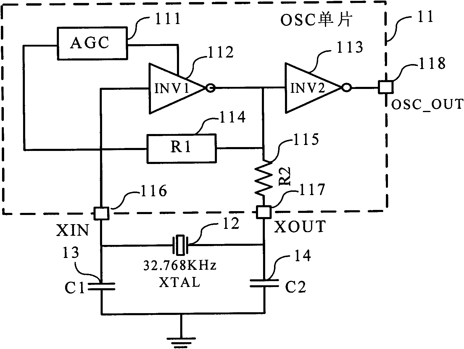
[0045] figure 2 It is a circuit block diagram of a crystal oscillator with low power consumption and fast start-up, which can be programmed to adjust the start-up conditions of the embodiment of the present invention. The XIN and XOUT pins are respectively connected to the load capacitors C1 and C2 of the crystal oscillator, and the 32.768KHz crystal oscillator XTAL is connected between the XIN and XOUT pins. 111 is an automatic gain control loop AGC with a π-type filter inside, the output end of AGC is connected to the bias end of INV1 inverting amplifier 112, the output end of INV1 inverting amplifier 112 is connected in series with the input end of INV2 inverting amplifier chain 113, Also connect one end of R1 feedback resistor 114 and R2 power current limiting resistor 115 at the series connection end, the other end of R1 feedback resistor connects the input end of AGC, the input end of INV1 inverting amplifier 112 and the XIN input end 116 of OSC monolithic 11, The XOUT...
Embodiment 2
[0057] Figure 6The overall circuit diagram of the crystal oscillator module of the embodiment of the present invention is given. The two transconductance amplifiers used as large resistances of this low-power, fast-starting crystal oscillator module that can be programmed to adjust the starting conditions share a self-bias Set the micro current source to provide bias voltage. The automatic gain control loop AGC includes an automatic gain control amplifier composed of C4, PM6, NM5, NM6 and resistor R3, and a π-type filter composed of resistor R2_E, capacitor C0 and C5. The VB3 bias is connected to the gate of the automatic gain control amplifier PM6, and the crystal oscillator signal from the XIN terminal is coupled to the gate of PM6 through the DC blocking capacitor C4 to provide the detected crystal oscillator signal for the input terminal of the AGC loop. The drain of the automatic gain control amplifier PM6 is connected to the input terminal Vi of the π-type filter, and ...
Embodiment 3
[0062] The two transconductance amplifiers of the crystal oscillator module in Embodiment 3 of the present invention use a programmable and adjustable self-bias micro-current source to provide the bias voltage VB2 respectively, see Figure 7a . Two independent self-biased micro-current sources are used to provide bias for the two transconductance amplifiers respectively, and R1-E and R2-E are independently programmed and controlled to realize precise control of the resistance values of R1-E and R2-E.
[0063] As a preference, Figure 7b An electrical block diagram of a self-biased micro-current source shared by two micro-current source transconductance amplifiers in Embodiment 2 of the present invention is given. The two micro-current source transconductance amplifiers R1_E and R2_E share a programmable and adjustable micro-current source 73 to realize uniform programming control of the resistance values of R1-E and R2-E. Compared with Embodiment 3 of the present inventi...
PUM
 Abstract
Description
Claims
Application Information
 - R&D
- Intellectual Property
- Life Sciences
- Materials
- Tech Scout
- Unparalleled Data Quality
- Higher Quality Content
- 60% Fewer Hallucinations
Browse by: Latest US Patents, China's latest patents, Technical Efficacy Thesaurus, Application Domain, Technology Topic, Popular Technical Reports.
© 2025 PatSnap. All rights reserved.Legal|Privacy policy|Modern Slavery Act Transparency Statement|Sitemap|About US| Contact US: help@patsnap.com


