Surge absorption device
A surge absorption and varistor technology, applied in circuit devices, emergency protection circuit devices, emergency protection circuit devices for limiting overcurrent/overvoltage, etc., can solve the problem of expensive maintenance costs, low surge absorption efficiency, Complex production process and other problems, to achieve the effect of improving efficiency, beautiful and tidy PCB layout, and reducing costs
- Summary
- Abstract
- Description
- Claims
- Application Information
AI Technical Summary
Problems solved by technology
Method used
Image
Examples
Embodiment 1
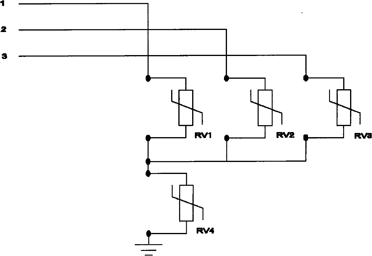
[0024] When the equipment to be protected works in a three-phase four-wire system, the circuit connection schematic diagram of the surge absorbing device of this embodiment is as follows figure 1 As shown, a surge absorbing device includes 4 decoupling units, that is, 4 varistors. The varistor voltages of the varistors used in the 220V AC power supply system are AC 210V and AC 300V, and the flow capacity is Microsecond-level surge signal; the varistor voltage of the varistor used in the 380V AC power supply system is AC 300V and AC 385V, and the flow capacity is microsecond-level surge signal; the four varistors are respectively RV1 and RV2 , RV3 and RV4, one end of them is connected together, and the other end is respectively connected to the input end of the equipment to be protected. RV4 is connected to the access end of the protection ground, and RV1, RV2 and RV3 are connected to the input end of the three-phase power line of the equipment to be protected.
Embodiment 2
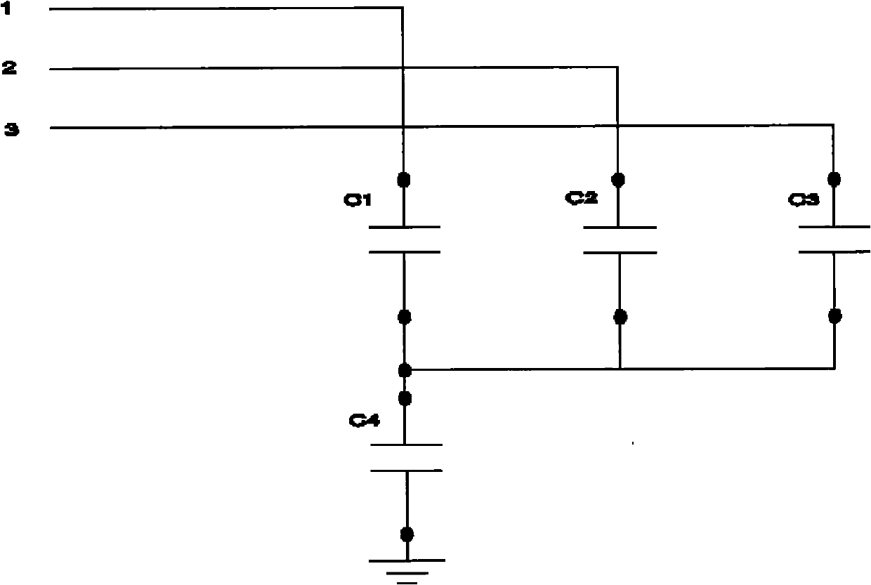
[0026] When the equipment to be protected works in a three-phase four-wire system, the circuit connection schematic diagram of the surge absorbing device of this embodiment is as follows figure 2 As shown, a surge absorbing device includes 4 decoupling units, that is, 4 safety capacitors. The capacitance of the safety capacitors is 10nF and 100nF, and the rated voltage is AC 250V and AC 275V; 4 safety capacitors The capacitors are respectively C1, C2, C3 and C4, one end of which is connected together, and the other end is respectively connected to the input end of the device to be protected. C4 is connected to the access end of the protection ground, and C1, C2 and C3 are connected to the input end of the three-phase power line of the equipment to be protected.
Embodiment 3
[0028] When the equipment to be protected works in a three-phase four-wire system, the circuit connection schematic diagram of the surge absorbing device of this embodiment is as follows image 3 As shown, the surge absorbing device includes four decoupling units: decoupling unit 1 , decoupling unit 2 , decoupling unit 3 , and decoupling unit 4 . Decoupling unit 1 is composed of C1 and RV1 in parallel, decoupling unit 2 is composed of C2 and RV2 in parallel, decoupling unit 3 is composed of C3 and RV3 in parallel, decoupling unit 4 is composed of C4 and RV4 in parallel, where C1, C2, C3 and C4 are safety capacitors, the capacitance of the safety capacitors is 10nF and 100nF, and the rated voltage is AC 250V and AC 275V; RV1, RV2, RV3 and RV4 are varistors, which are used in the 220V AC power supply system. The varistor voltage of the varistor is AC 210V and AC 300V, and the flow capacity is a microsecond surge signal; the varistor used in the 380V AC power supply system has a ...
PUM
 Abstract
Description
Claims
Application Information
 - R&D
- Intellectual Property
- Life Sciences
- Materials
- Tech Scout
- Unparalleled Data Quality
- Higher Quality Content
- 60% Fewer Hallucinations
Browse by: Latest US Patents, China's latest patents, Technical Efficacy Thesaurus, Application Domain, Technology Topic, Popular Technical Reports.
© 2025 PatSnap. All rights reserved.Legal|Privacy policy|Modern Slavery Act Transparency Statement|Sitemap|About US| Contact US: help@patsnap.com


