Battery protection integrated circuit and system

An integrated circuit and battery technology, applied in emergency protection circuit devices, circuits, and secondary battery repair/maintenance, etc., can solve problems such as hidden safety hazards, inability to meet high voltage tolerance, etc., to reduce costs, reduce on-resistance, and reduce small chips area effect

Active Publication Date: 2011-04-06
WUXI ZGMICRO ELECTRONICS CO LTD
View PDF5 Cites 34 Cited by
  • Summary
  • Abstract
  • Description
  • Claims
  • Application Information

AI Technical Summary

Problems solved by technology

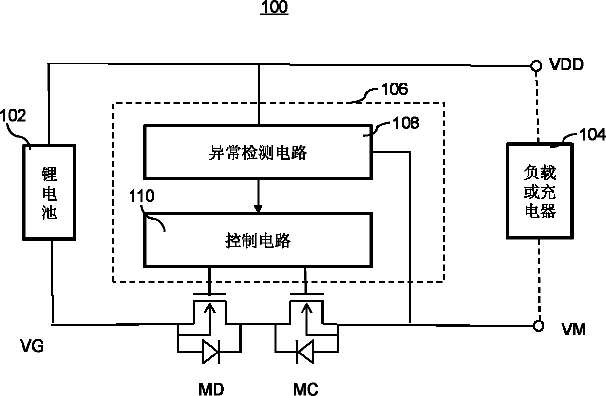
[0006] On the other hand, the source and drain terminals of the MOSFET devices manufactured by the planar manufacturing process are all on the top of the silicon wafer. This process is conducive to integrating multiple devices on one chip to achieve high integration, small size, The advantages of simple process and low cost, specific to figure 1 When the system shown is manufactured, it is possible to integrate the charge protection switch MC and discharge protection switch MD, abnormality detection circuit and control circuit on one chip, but the disadvantage of this process is that the abnormality detection circuit and control circuit usually use low-voltage devices , if the same process is used in manufacturing, then the charge protection switch MC and discharge protection switch MD will also be made into low-voltage devices
Although the on-resistance of the low-voltage MOD switch tube is small, it can meet the requirements for on-resistance in this application, but it cannot meet the requirements for high-voltage tolerance in this application.
Although some manufacturers have adopted such a scheme in order to save costs and reduce the volume of finished products, in fact it leaves a great potential safety hazard

Method used


Image

  • Battery protection integrated circuit and system
  • Battery protection integrated circuit and system
  • Battery protection integrated circuit and system

Examples


Embodiment Construction

[0033] The detailed description of the present invention directly or indirectly simulates the operation of the technical solution of the present invention mainly through programs, steps, logic blocks, processes or other symbolic descriptions. In the ensuing description, numerous specific details are set forth in order to provide a thorough understanding of the present invention. Rather, the invention may be practiced without these specific details. These descriptions and representations herein are used by those skilled in the art to effectively convey the substance of their work to others skilled in the art. In other words, for the purpose of avoiding obscuring the present invention, well-known methods, procedures, components and circuits have not been described in detail since they are readily understood.

[0034]Reference herein to "one embodiment" or "an embodiment" refers to a particular feature, structure or characteristic that can be included in at least one implementat...


PUM


Abstract

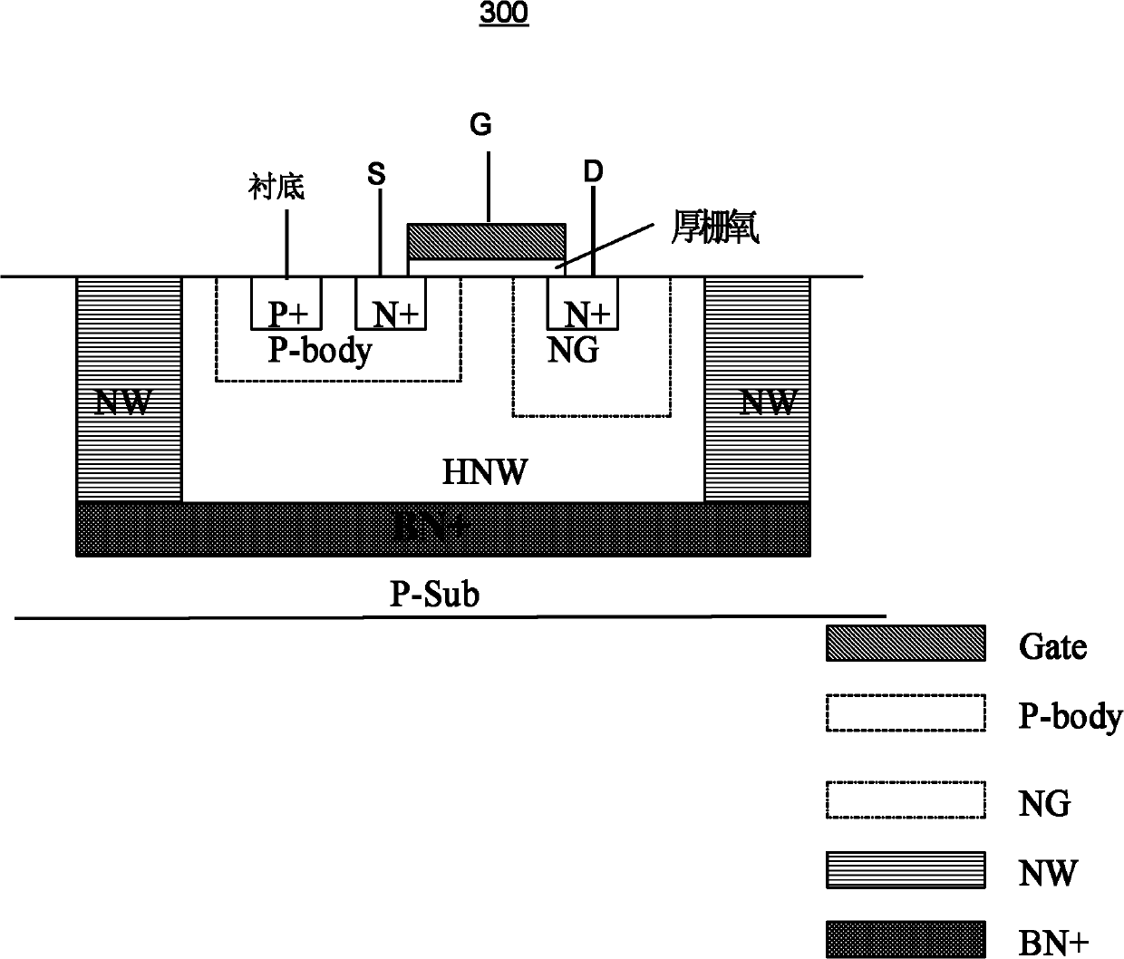
The invention discloses a battery protection integrated circuit which comprises an MOS (metal oxide semiconductor) switching tube and a protection control circuit, wherein, one end of the switching tube is connected with a battery, and the other end of the switching tube is connected with load or a charger; the protection control circuit and the MOS switching tube are integrated on the same wafer; the protection control circuit generates a control signal according to the battery charging or discharging situation to control conduction or switch-off of the MOS switching tube, wherein, the thickness of a gate oxide layer of the MOS switching tube is more than the thickness of the gate oxide layer of an MOSFET (metal-oxide-semiconductor field effect transistor) device in the protection control circuit; and the MOS switching tube can be an asymmetric isolation high-voltage MOS tube. In the invention, by adopting a plane manufacturing process, the high-voltage MOSFET tube, a control circuitand the like are integrated on the same chip, thus reducing the cost, saving the chip area and meeting the demand for high-voltage endurance capability in the application.

Description

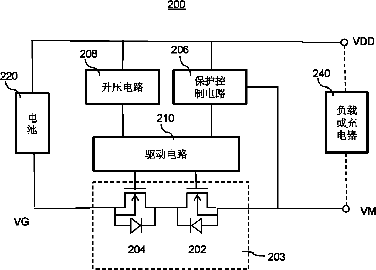
【Technical field】 [0001] The invention relates to the field of battery protection, in particular to a battery protection circuit integrating a high-voltage protection switch tube on the same chip. 【Background technique】 [0002] Since lithium-ion batteries have no memory effect, they are gradually replacing traditional nickel-metal hydride batteries in more and more electronic systems and becoming the main power source in portable electronic devices. But lithium batteries have many safety issues. Therefore, complex battery protection circuits exist in lithium battery systems to ensure that unsafe conditions are prevented from causing battery damage in various unexpected situations. [0003] Please refer to figure 1 , which shows a conventional lithium battery protection circuit system 100 . Between the negative pole VG of the lithium battery 102 and the load or the negative pole VM of the charger 104, there is a charge protection switch MC and a discharge protection switc...

Claims


Application Information

Patent Timeline
Patent Type & Authority Applications(China)
IPC IPC(8): H02H7/18H01M10/42
CPCY02E60/12H01L21/761H01L29/0878H01L29/7816
Inventor 王钊尹航杨晓东
Owner WUXI ZGMICRO ELECTRONICS CO LTD
Why Eureka
Try Eureka