
Control circuit and method of buck-boost power converter

A control circuit and control method technology, applied in control/regulation systems, output power conversion devices, instruments, etc., can solve problems such as unsatisfactory users, and achieve the effect of improving stability

Inactive Publication Date: 2011-03-30
RICHTEK TECH
View PDF3 Cites 15 Cited by
  • Summary
  • Abstract
  • Description
  • Claims
  • Application Information

AI Technical Summary

Problems solved by technology

However, the output voltage Vo of this buck-boost power converter is a negative voltage, which is not suitable for some applications, so there are such Figure 4 The buck-boost power stage 16 shown can step down or boost the input voltage Vin to a positive output voltage Vo
At present, many control circuits and methods for operating the buck-boost power stage 16 have been proposed, such as US Patent Nos. 6,166,527 and 7,518,346, but they still cannot meet the needs of users
[0004] Therefore, there are above-mentioned inconveniences and problems in the control circuit and method of the known buck-boost power converter.

Method used


Image

  • Control circuit and method of buck-boost power converter
  • Control circuit and method of buck-boost power converter
  • Control circuit and method of buck-boost power converter

Examples


Embodiment Construction

[0099] The present invention will be further described below in conjunction with embodiment and accompanying drawing.

[0100] see now Figure 5 , Figure 5 It is a schematic diagram of an embodiment of the present invention. As shown in the figure, the buck-boost power converter 18 includes a control circuit 20 that provides signals S1, S2, S3 and S4 to respectively drive the power switches Q1, Q2, Q3 and Q4 of the buck-boost power stage 16, so as to The input voltage Vin is stepped down or boosted to become the output voltage Vo. In the control circuit 20, the feedback circuit 22 detects the output voltage Vo to generate a feedback signal VFB related to the output voltage Vo, and the error amplifier 24 amplifies the difference between the feedback signal VFB and the reference voltage Vref1 to generate an error signal Vc, The waveform generator 26 provides the sawtooth wave signals Vramp1 and Vramp2, the pulse width modulation comparator 28 generates the pulse width modula...


PUM


Abstract

The invention discloses a control circuit of a buck-boost power converter, which is used for generating a control signal for manipulating a buck-boost power level and also used for converting an input voltage into an output voltage, and is characterized by comprising a feedback circuit, an error amplifier, a waveform generator, a frequency controller, a frequency generator, a pulse width modulation comparator and a gate driver. The control circuit and control method of the buck-boost power converter have the advantages of improving the stability of the buck-boost power converter, reducing the switching loss of the buck-boost power level and improving the efficiency of the buck-boost power converter.

Description

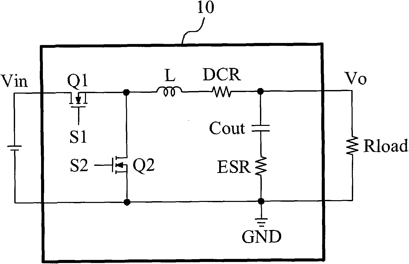
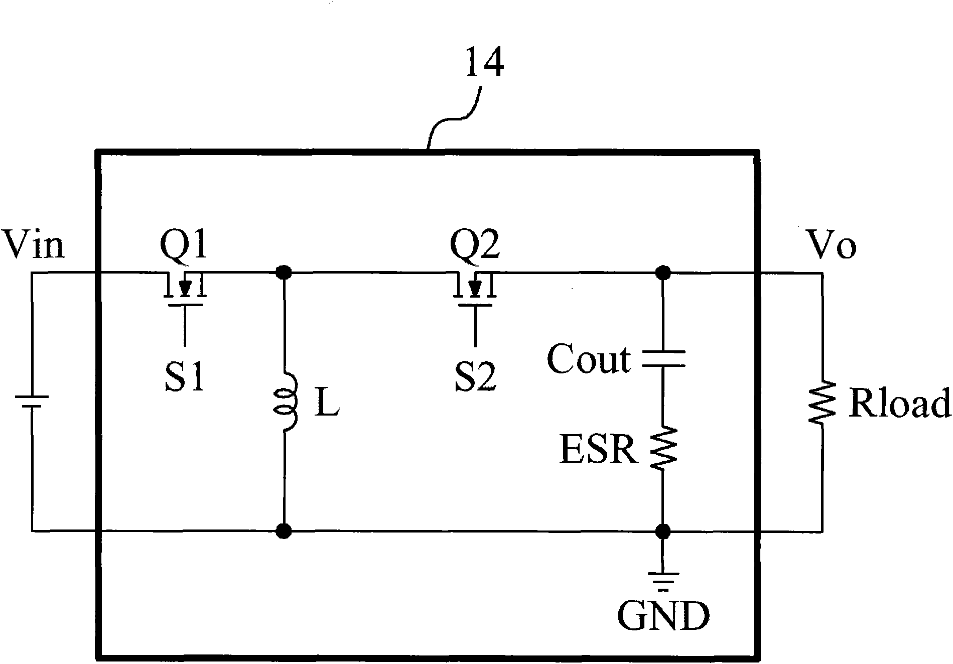
technical field [0001] The invention relates to a buck-boost power converter, in particular to a control circuit and method for a buck-boost power converter. Background technique [0002] The step-down power converter is operated as figure 1 The step-down power stage 10 shown steps down the input voltage Vin to an output voltage Vo to supply the load Rload. The boost power converter is operated as figure 2 The boost power stage 12 shown in the figure boosts the input voltage Vin to an output voltage Vo to supply the load Rload. Because the battery cannot provide a stable voltage all the time, a system using the battery as the input power Vin, such as a portable device, cannot use a buck power converter or a boost power converter to provide a stable voltage. [0003] Since the voltage of the battery will drop with the consumption of electric energy, the system using the battery as the input power source needs a power converter capable of switching between buck and boost. ...

Claims


Application Information

Patent Timeline
IPC IPC(8): H02M3/158
Inventor 陈文玮刘国基
Owner RICHTEK TECH
Learn More