Tyre forming apparatus

A tire forming and tire technology, applied in tires, other household appliances, household appliances, etc., can solve the problems of reduced production efficiency, time and labor consumption, etc., and achieve the effect of improving tire quality

Active Publication Date: 2015-04-01
SUMITOMO RUBBER IND LTD
View PDF3 Cites 0 Cited by
  • Summary
  • Abstract
  • Description
  • Claims
  • Application Information

AI Technical Summary

Problems solved by technology

However, in this case, the replacement work requires time and labor, which causes a significant decrease in production efficiency.

Method used


Image

  • Tyre forming apparatus
  • Tyre forming apparatus
  • Tyre forming apparatus

Examples


Embodiment Construction

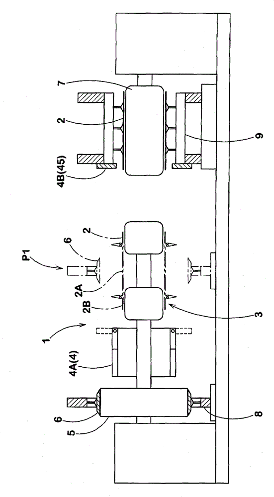
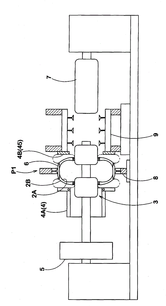
[0038] Next, embodiments of the present invention will be described in detail. figure 1 , figure 2 It is a side view schematically showing an example of a tire building line using the tire building apparatus of the present invention.

[0039] exist figure 1 , figure 2 Among them, the tire building apparatus 1 of the present embodiment includes: a shaping drum 3 that holds a cylindrical tire casing 2 including a carcass, expands the casing main body portion 2A into a ring shape, and simultaneously expands the casing protruding portion 2B is rolled up; the crimping unit 4 crimps and joins the above-mentioned rolled up case extension portion 2B to the ring-shaped case main body portion 2A.

[0040] here, figure 1 , figure 2 The middle symbol 5 is a so-called belt drum, for example, by sequentially winding tread constituent members including a belt ply, a tread reinforcing cord such as a belt ply, and a tread rubber around the belt drum 5 . On the outer peripheral surf...


PUM


Abstract

The present invention provides a tyre forming apparatus, capable of preventing a pressing body from a ply turn gas bag, preventing production efficiency from reducing, and improving service life of the ply turn gas bag. The apparatus includes a crimp connection unit, that is shaped by a shaping drum and two ends of which are crimped by a coiled housing projection part and joined to an annular housing main body. The crimp connection unit arranged on one side of a feeding tread ring has the pressing body, which moves toward an inner side in an axial center direction through a moving barrel to join a projection part to the housing main body by means of the ply turn gas bag. The pressing body is composed of a plurality of presser blades arranged in a circumferential direction, one end of each presser blade is supported by a shaft fixing point arranged on inner end part in the axial center direction of the moving barrel in a shaft manner, such that the presser blade can be switched between a standing state and a falling state, wherein the standing state is that the other end stands toward an external side in a radial direction to be of a circular disk shape, and the falling state is that the other end falls down toward the external side in the axial center direction such that the pressing body is of a cylinder shape to make the tread ring to be in a crossing state.

Description

technical field [0001] The invention relates to a tire building device capable of improving the service life of a cord turn-up air bag. Background technique [0002] A sizing drum A is usually used when forming a green tire, such as Figure 8 As schematically shown in (A) and (B), bead cores c are arranged on both sides in the axial direction of a cylindrical tire case b held across a pair of drum portions A1 , A1 . In addition, by expanding the shell body portion b1 between the bead cores c and c into a ring shape, the shell body portion b1 is crimped and joined to the ring-shaped bead that has been carried in advance into the radially outer standby position P1. The inner peripheral surface of the tread ring d. In addition, the shell projecting portion b2 on the outer side in the axial direction of the bead core c is wound up around the bead core c by the carcass turnup bag B provided in the drum portion A1. [0003] Additionally, if Figure 9 As schematically shown, the...

Claims


Application Information

Patent Timeline
Patent Type & Authority Patents(China)
IPC IPC(8): B29D30/20B29D30/32
Inventor 乙胁仁诗
Owner SUMITOMO RUBBER IND LTD
Why Eureka
Try Eureka