Rotary electric machine and method for mounting coil on core for rotary electric machine

Inactive Publication Date: 2005-10-06
TOYOTA IND CORP
View PDF5 Cites 26 Cited by
  • Summary
  • Abstract
  • Description
  • Claims
  • Application Information

AI Technical Summary

Benefits of technology

[0011] Accordingly, it is an objective of the present invention to provide a rotary electric machine and a method for mounting a coil of a core for a rotary electric machine that reliably ensures the lamination factor for the coil in slots and improves the output characteristics of the rotary electric machine without decreasing production efficiency.

Problems solved by technology

However, when the coil pieces of the Japanese Laid-Open Patent Publication No. 10-66314 are used in some slots where the open end of each slot in harrowed, the coil side wires of the coil piece that has earlier been inserted in the slot might block the opening of the slot from inside depending on the position and shape of the openings.
This might obstruct insertion of the subsequent coil pieces into the slot.
Therefore, according to the method for mounting a coil described in Japanese Laid-Open Patent Publication No. 10-66314, the number of coils that are inserted in each slot cannot be increased in some positions where the opening of each slot is narrow.
If so, as the lamination factor of the coils in each slot cannot be improved, the output characteristics of the rotary electric machine cannot be improved as desired.
However, the method requires a complicated operation for connecting the distal ends of the legs of the coil pieces through welding or the like after temporarily mounting the coil pieces to the slots.
This reduces production efficiency.

Method used


Image

  • Rotary electric machine and method for mounting coil on core for rotary electric machine
  • Rotary electric machine and method for mounting coil on core for rotary electric machine
  • Rotary electric machine and method for mounting coil on core for rotary electric machine

Examples


Embodiment Construction

[0030] A method for mounting a coil to a stator core of a motor 10 according to one embodiment of the present invention will how be described with reference to FIGS. 1 to 8. The motor 10 is one type of a rotary electric machine.

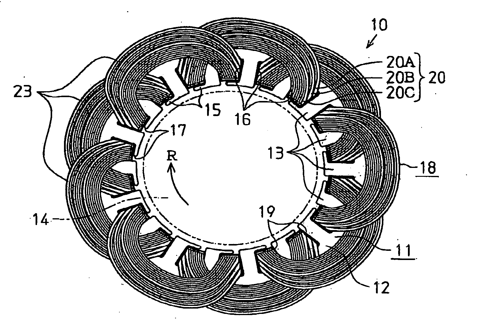
[0031]FIG. 1 shows a part of a rotary electric machine, which is the motor 10 in this embodiment. As shown in FIG. 1, a core for a rotary electric machine, a stator core 11 in this embodiment, has a cylindrical core body 12 formed of laminated steel sheets. Teeth 13 project radially inward from the inner circumferential surface of the core body 12 with an equal pitch in the circumferential direction of the stator. Each tooth 13 has a projection 15 at its distal end. Each projection 15 extends along a direction opposite to the rotation direction R of a rotor core 14 shown by a chain double-dashed line in FIG. 1 so that the teeth 13 are L-shaped. A slot 16 is formed between the adjacent teeth 13 extending along the axial direction of the core body 12. In the p...


PUM

PropertyMeasurementUnit
Lengthaaaaaaaaaa
Depthaaaaaaaaaa

Abstract

A method for mounting a coil onto a stator for a rotary electric machine. The method includes forming a coil piece by winding wire having a flat cross section into a single row lamination state including wire layers that are aligned along a line that is perpendicular to flat surfaces of the wire. The coil piece is formed so that a first portion to be inserted in the slot and a second portion that is not inserted in the slot appear alternately along the coil piece. The method also includes displacing the wire layers at the first portion from one another to change the single row lamination state to a connectively laminated stat e in which the wire layers at the portion to be inserted in the slot each adjacent pair of the wire layers partially overlap with respect to a direction perpendicular to the flat surfaces of the wire. The method further includes inserting the wires of the first portion into the slot, by passing each of the wire layers through the opening of the slot successively from the wire layer at the top of the lamination and displacing each of the wire layers at the first portion from each other.

Description

BACKGROUND OF THE INVENTION [0001] The present invention relates to a rotary electric machine and a method for mounting a coil on a core for a rotary electric machine. [0002] A typical rotary electric machine such as a motor and a generator is formed by disposing a coil onto a core that is used for a rotary electric machine, in which a stator (or a rotor) is formed of laminated steel sheets. For example, when a stator core is used, teeth are formed in the inner circumferential surface (or outer circumferential surface) of the stator core and a stator is formed by inserting a coil in slots formed between the teeth. The coil is formed from a conductive wire insulated with a coating. Conventionally, wires having a circular cross-section have been used. However, wires having a flat cross-section such as oval or rectangular have come into use as described in Japanese Laid-Open Patent Publication No. 10-66314 to improve the output characteristics of the rotary electric machine by increasi...

Claims


Application Information

Patent Timeline
IPC IPC(8): H02K3/04H02K15/04H02K3/12H02K15/06H02K15/085
CPCH02K15/04H02K15/06H02K15/085Y10T29/49169Y10T29/49073Y10T29/49194Y10T29/49071Y10T29/49195H02K15/0478
Inventor FUKASAKU, HIROSHIUETSUJI, KIYOSHIADANIYA, TAKU
Owner TOYOTA IND CORP
Why Eureka
Try Eureka