
Full-automatic bearing greasing and capping machine

A capping machine, fully automatic technology, applied in the direction of engine components, engine lubrication, conveyors, etc., can solve the problems of inconvenient maintenance, complex design, poor synchronization, etc., to achieve easy debugging and installation of tooling molds, high production qualification rate , The effect of accurate positioning accuracy

Inactive Publication Date: 2011-03-02
SHANDONG XUNJIE PRECISION EQUIP
View PDF4 Cites 19 Cited by
  • Summary
  • Abstract
  • Description
  • Claims
  • Application Information

AI Technical Summary

Problems solved by technology

[0002] The existing gland device fixes the oil pressure booster cylinder by installing a thick steel plate on four columns. When the operator adjusts, he must operate in the gap of the guide column, which is very inconvenient for maintenance and debugging; The ball screw is used to drive up and down, which increases the manufacturing cost and is not easy to maintain; the unqualified product rejection device uses two cylinders to push out the unqualified product, wasting energy
The greasing part is put together with a cylinder and an oil injection valve, which has low efficiency, high failure rate, and poor synchronization; in summary, the existing bearing greasing and capping machine is large in size, complex in design, and the connection between various parts is messy and cumbersome. , laborious operation, inconvenient maintenance, high failure rate, and serious energy waste during use; the existing equipment is 6 to 7s / set, and the efficiency is quite low

Method used


Image

  • Full-automatic bearing greasing and capping machine
  • Full-automatic bearing greasing and capping machine
  • Full-automatic bearing greasing and capping machine

Examples


Embodiment Construction

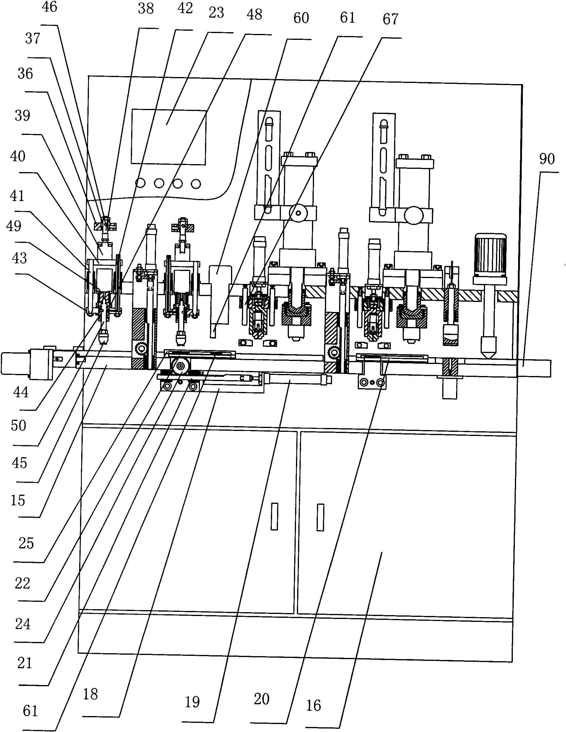
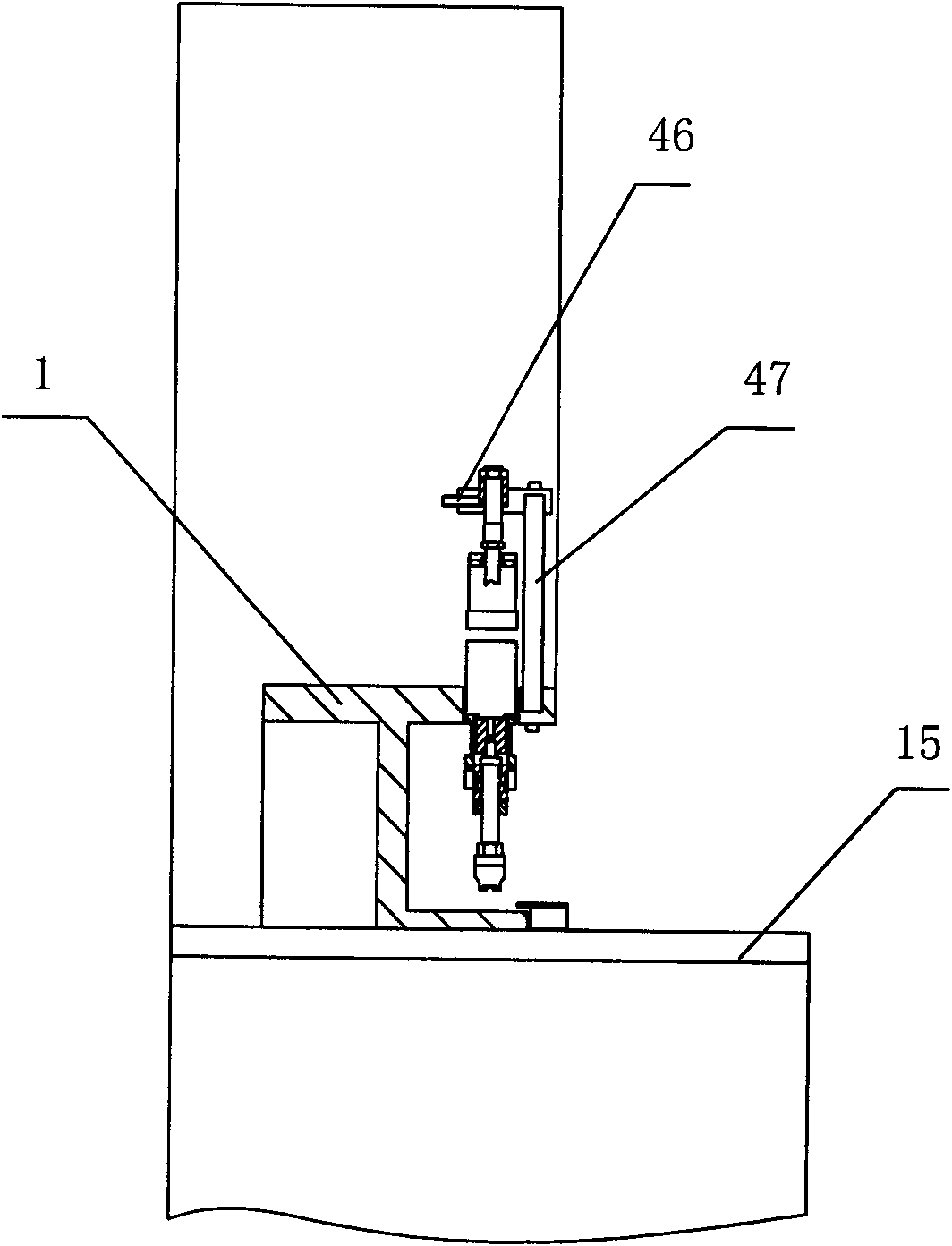
[0015] Such as figure 1 , figure 2As shown, a fully automatic bearing fatting and capping machine includes a frame 16, a control device 23, a workbench 15, a mounting seat 1, a raw material conveying device, a fatting device, a grease amount detection device, a capping device, and a capping device. device, stand-up device, dust cover height detection device, fat equalizing device and unqualified product rejecting device, it is characterized in that a workbench 15 is fixed on the frame 16, a mounting seat 1 is fixed on the workbench 15, and the front of the mounting seat 1 There is a supporting plate 17 at the bottom, a control device 23 is provided on the top of the mounting seat 1, a raw material conveying device is provided on the left side of the workbench 15, and a rejecting device is provided on the right side; The processing sequence is arranged from left to right: two grease adding devices, grease amount detection device, two capping devices and capping device, dust c...


PUM


Abstract

The invention discloses a full-automatic greasing and capping machine, relating to a device for adding grease and a dust cap to a bearing. A workbench is fixed on a machine frame; a mounting base is fixed on the workbench; the front part of the mounting base is provided with a material support plate; the upper part of the mounting base is provided with a control device; the left side of the workbench is provided with a material conveyor, and the right side of the workbench is provided with an unacceptable product removing device; according to the processing sequence, two greasing devices, a grease quantity detection device, two capping devices, a dust cap height detection device and a grease equalizer are sequentially arranged on the mounting base from left to right; turning devices are respectively arranged between the two greasing devices and between the two capping devices; and a front reciprocating device and a rear reciprocating device are respectively arranged below the workbench. The full-automatic greasing and capping machine disclosed by the invention integrates the stations and the mounting base into a whole, is high in positioning accuracy and facilitates debugging and installation of a fixture mold; and the total seal shell is convenient for cleaning and maintenance, thus, the invention has the advantages of strong dustproof capacity, low danger coefficient, low failure rate and high product qualification rate.

Description

technical field [0001] The invention relates to a device for adding grease and a dust-proof cover to a bearing, in particular to a fully automatic bearing adding grease and capping machine. Background technique [0002] The existing gland device fixes the oil pressurized cylinder by installing a thick steel plate on four columns. When the operator adjusts, he must operate in the gap of the guide column, which is very inconvenient for maintenance and debugging; The ball screw is used to drive up and down, which increases the manufacturing cost and is not easy to maintain; the rejecting device for rejecting the defective product uses two cylinders to push out the rejecting product, which wastes energy. The greasing part is pieced together with a cylinder and an oil injection valve, which has low efficiency, high failure rate, and poor synchronization; in summary, the existing bearing greasing and capping machine is large in size, complex in design, and the connection between v...

Claims


Application Information

Patent Timeline
Patent Type & Authority Applications(China)
IPC IPC(8): F16N7/14F16N39/00F16N27/00B23P19/027B66F19/00B65G15/00
Inventor 曲建华宋艳
Owner SHANDONG XUNJIE PRECISION EQUIP
Learn More