Casting blank transverse moving mechanism
A technology of traversing mechanism and casting slab, which is applied in the field of metallurgy, can solve the problems of unable to meet the billet discharge cycle of the casting machine, the structure of the transfer machine is complex, and the casting billet cycle is long, so as to achieve small space occupation, improve billet discharge efficiency, and cycle time short effect
- Summary
- Abstract
- Description
- Claims
- Application Information
AI Technical Summary
Problems solved by technology
Method used
Image

Examples
Embodiment 1
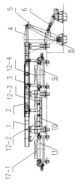
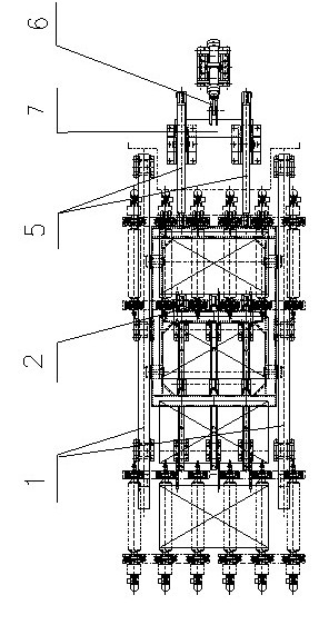
[0020] Embodiment 1, a slab traversing mechanism, including a traversing trolley 2 and a driving device, the traversing trolley 2 is connected to the driving device, a slide rail 10 is provided between the first-stage roller table 9 and the second-stage roller table 11, and the sliding A guide rail 1 is provided above the rail 10, and the traverse trolley 2 is placed on the guide rail 1 and can move along the guide rail 1. Three push heads 3 are arranged on the traverse trolley 2; two parking positions are provided on the slide rail 10, and the driving device Including connecting rod 4, swing rod 5 and hydraulic cylinder 6, one end of connecting rod 4 is connected with traverse trolley 2, the other end is flexibly connected with one end of swing rod 5, and the other end of swing rod 5 is flexibly connected with swing rod base 8, Two connecting rods 4 are respectively connected to two swing rods 5, and the hydraulic cylinder 6 is connected to the swing rod 5 through the cross ro...
Embodiment 2
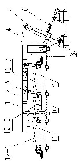
[0022] Embodiment 2, a slab traversing mechanism, including a traversing trolley 2 and a driving device, the traversing trolley 2 is connected to the driving device, a slide rail 10 is provided between the first-stage roller table 9 and the second-stage roller table 11, and the sliding A guide rail 1 is provided above the rail 10, and the traverse trolley 2 is placed on the guide rail 1 and can move along the guide rail 1. Two push heads 3 are arranged on the traverse trolley 2; a parking position is provided on the slide rail 10, and the driving device Including connecting rod 4, swing rod 5 and hydraulic cylinder 6, one end of connecting rod 4 is connected with traverse trolley 2, the other end is flexibly connected with one end of swing rod 5, and the other end of swing rod 5 is flexibly connected with swing rod base 8, Two connecting rods 4 are respectively connected to two swing rods 5, and the hydraulic cylinder 6 is connected to the swing rod 5 through the cross rod 7 an...
Embodiment 3
[0024] Embodiment 3, a slab traversing mechanism, including a traversing trolley 2 and a driving device, the traversing trolley 2 is connected to the driving device, a slide rail 10 is provided between the first-stage roller table 9 and the second-stage roller table 11, and the sliding A guide rail 1 is arranged above the rail 10, and the traverse trolley 2 is placed on the guide rail 1 and can move along the guide rail 1. Four push heads 3 are arranged on the traverse trolley 2; three parking positions are arranged on the slide rail 10, and the driving device Including connecting rod 4, swing rod 5 and hydraulic cylinder 6, one end of connecting rod 4 is connected with traverse trolley 2, the other end is flexibly connected with one end of swing rod 5, and the other end of swing rod 5 is flexibly connected with swing rod base 8, Two connecting rods 4 are respectively connected to two swing rods 5, and the hydraulic cylinder 6 is connected to the swing rod 5 through the cross r...
PUM
 Abstract
Description
Claims
Application Information
 - R&D
- Intellectual Property
- Life Sciences
- Materials
- Tech Scout
- Unparalleled Data Quality
- Higher Quality Content
- 60% Fewer Hallucinations
Browse by: Latest US Patents, China's latest patents, Technical Efficacy Thesaurus, Application Domain, Technology Topic, Popular Technical Reports.
© 2025 PatSnap. All rights reserved.Legal|Privacy policy|Modern Slavery Act Transparency Statement|Sitemap|About US| Contact US: help@patsnap.com