
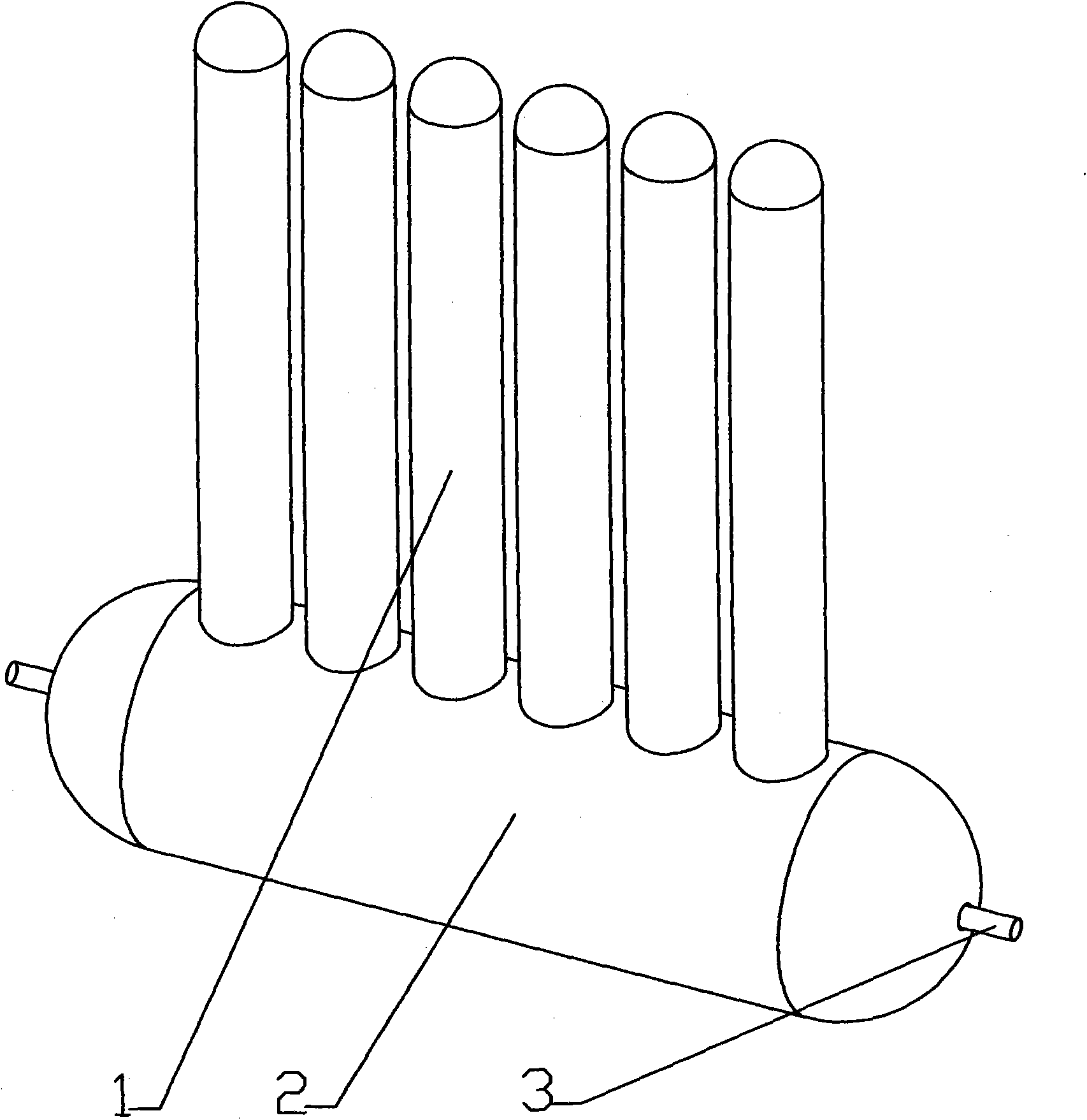
Solar water heater with solar thermal collector pipes mounted above hot water storage tank

A solar collector tube, solar water heater technology, applied to solar collectors, solar collectors using working fluids, solar thermal devices, etc. High problems, to achieve the effect of wide heat absorption area, overcoming unusability, and high heat utilization rate

Inactive Publication Date: 2011-01-26
杭州慈源科技有限公司
View PDF5 Cites 6 Cited by
  • Summary
  • Abstract
  • Description
  • Claims
  • Application Information

AI Technical Summary

Problems solved by technology

The natural circulation hot water system composed of them often relies on the density difference generated by the difference in water temperature between the collector and the water storage tank for temperature difference circulation (thermosiphon circulation), and its water circulation speed is high, and the heat utilization rate is not high.
At present, the inner and outer tubes and joints of vacuum solar collector tubes commonly used are rigid connections of glass inner and outer tubes. The surface of the inner tube is coated to improve the absorption rate of solar radiation. Like a very slender thermos bottle, this kind of heat collecting tube needs to be made of heat-resistant glass with a small thermal expansion coefficient, and the process is complicated and the cost is high. During the use process, due to hail, flying stones and other reasons, Once the outer tube breaks, the whole tube will be scrapped, and the heat absorption area is small, and the heat utilization rate is not high
The solar heat collecting tube of the existing solar water heater is below the water collecting tank, and the hot water is above, such a solar water heater is easy to be damaged

Method used


Image

  • Solar water heater with solar thermal collector pipes mounted above hot water storage tank
  • Solar water heater with solar thermal collector pipes mounted above hot water storage tank
  • Solar water heater with solar thermal collector pipes mounted above hot water storage tank

Examples


Embodiment Construction

[0015] The specific implementation of the solar water heater with the solar heat collecting tube installed above the heat storage tank of the present invention will be described in detail below in conjunction with the accompanying drawings.

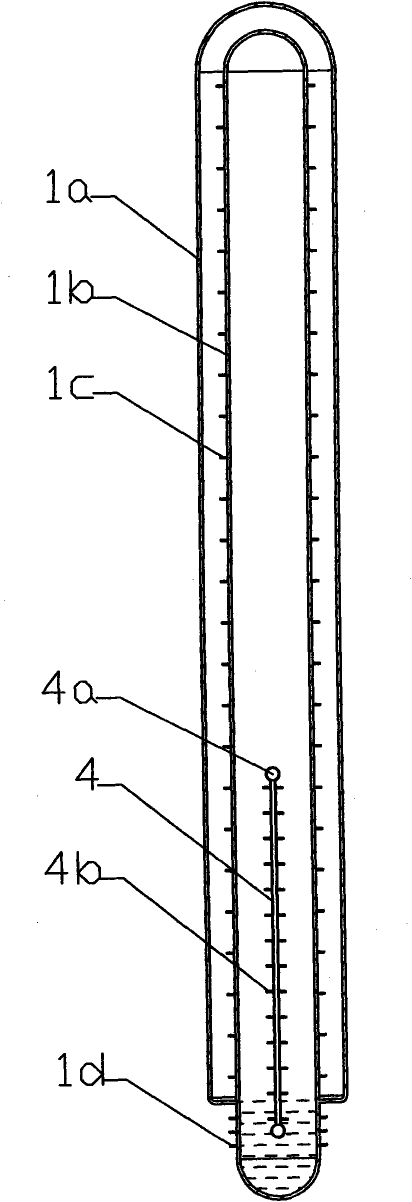
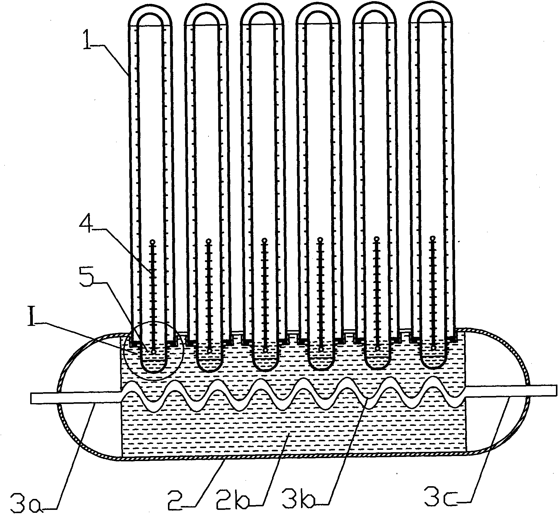
[0016] Such as figure 1 , 3 As shown, it is a structural diagram of a solar water heater in which the solar collector tube 1 of the present invention is installed above the heat storage tank 2, and it includes the solar collector tube 1, the thermal storage tank 2 and the inlet and outlet pipes 3, and is characterized in that: the solar collector The heat pipe 1 is a vacuum tube composed of inner and outer tubes (1b, 1a). There are inner fins 1c and outer fins 1d on the inner tube 1b. There are superconducting liquid 5 and capillary tubes 4 in the solar collector tube 1. There are capillary tubes 4 Fins 4b and capillary tubes 4 are fixed with rubber heads 4a; the solar heat collecting tube 1 is installed above the heat storage tank 2, an...


PUM


Abstract

The invention relates to a solar water heater with solar thermal collector pipes mounted above a hot water storage tank. The solar water heater comprises solar thermal collector pipes, a hot water storage tank, an intake pipe and a drainage pipe and is characterized in that each solar thermal collector pipe is a vacuum pipe comprising an inner pipe and an outer pipe, wherein the inner pipe is provided with internal fins and external fins, the solar thermal collector pipe is internally provided with superconducting fluid and capillaries, each capillary is provided with the fins, rubber heads are fixed at both ends of each capillary, and the solar thermal collector pipes are mounted above the hot water storage tank which is internally provided with a heat exchanger coil and a regenerative smoothing emulsion. The invention overcomes the defects of a traditional solar heat collector and has the advantages of simple manufacture process, rapid start, lower cost, reliable use, wide heat-absorbing area, high heat utilization rate and corrosion resistance, and the like.

Description

1. Technical field [0001] The invention relates to a solar water heater, in particular to a solar water heater in which a solar heat collecting tube is installed above a heat storage tank. 2. Background technology [0002] The use of solar energy is of great significance for taking the road of sustainable development, protecting the ecological environment on which human beings depend, and solving the energy supply problem of those without electricity. The efficient and pollution-free use of solar energy is even more important for saving energy and protecting the natural environment. It is meaningful. In the solar thermal utilization system, the key is how to efficiently collect sunlight and convert it into heat energy. At present, heat utilization is a comprehensive project in solar energy utilization technology. [0003] At present, solar collector tubes are generally open at one end and closed at the other end, that is, blind tubes. The natural circulation hot water sys...

Claims


Application Information

Patent Timeline
Patent Type & Authority Applications(China)
IPC IPC(8): F24J2/32F24J2/46F24S10/95
CPCY02E10/44
Inventor 王宝根
Owner 杭州慈源科技有限公司
Learn More