
Silent chain transmission device

A transmission device, silent chain technology, applied in the direction of transmission device, valve drive device, transmission chain, etc., can solve the problems of variable length, increased space occupation, increased weight of chain 920, etc., to reduce the number of parts and reduce the weight of the chain , reduce the effect of occupying space

Inactive Publication Date: 2011-01-12
TSUBAKIMOTO CHAIN CO
View PDF7 Cites 7 Cited by
  • Summary
  • Abstract
  • Description
  • Claims
  • Application Information

AI Technical Summary

Problems solved by technology

[0012] However, for the known silent chain drive, since the outermost row in the width direction of the chain 920 is provided with a guide plate 931, the guide plate 931 is located at the outermost row in the width direction of the chain 920 and is related to the rotation of the chain 920 and the sprocket wheel 910. Transmission independent, so the increased width of the chain 920 relative to the desired engagement width presents the problem of increased footprint
[0013] In addition, since the connecting pin 921 becomes longer, the bending of the chain when the tension load is applied becomes larger, and the outer peripheral surface of the connecting pin 921 contacts the inner peripheral surface of the bushing 922 on one side, or the fitting gap cannot be maintained and wear increases, resulting in Problems with the cause of vibration or noise
[0014] Furthermore, there are also problems in that the number of parts increases by having the guide plate 931, the man-hours required for assembly increase, the weight of the chain 920 itself increases by an amount corresponding to the length of the connecting pin 921 provided with the guide plate 931, and the speed change is followed. sex decline

Method used


Image

  • Silent chain transmission device
  • Silent chain transmission device
  • Silent chain transmission device

Examples


Embodiment 1

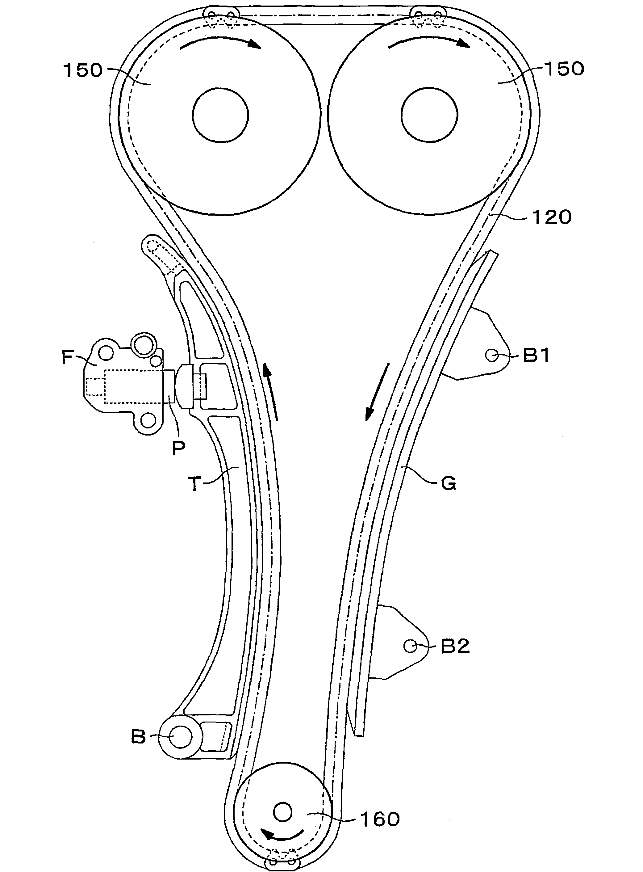
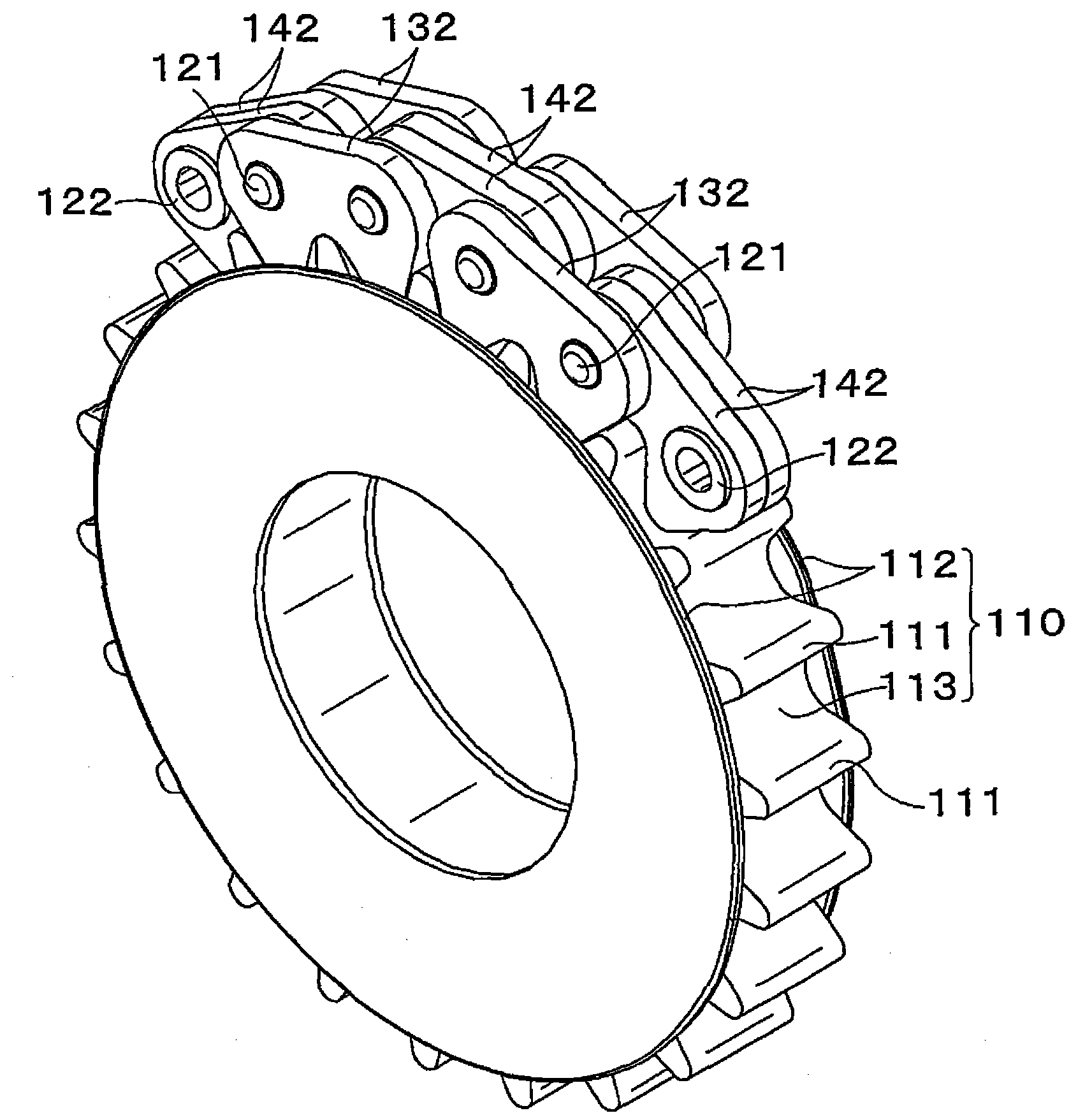
[0089] Such as Figure 2 to Figure 4As shown, the silent chain transmission 100 as the first embodiment of the present invention is composed of a chain 120 and a sprocket 110 (a driven sprocket 150 and a driving sprocket 160), and the above-mentioned chain 120 is composed of an outer chain link (a first chain link) row) and the inner chain link (the second chain link row) are alternately connected and woven through the connecting pin 121 and the bushing 122 so as to be able to bend. The sprocket 111 is provided on the outer peripheral surface, and the said convex part 112 guides the chain 120 on both outer sides of the sprocket 111. As shown in FIG.

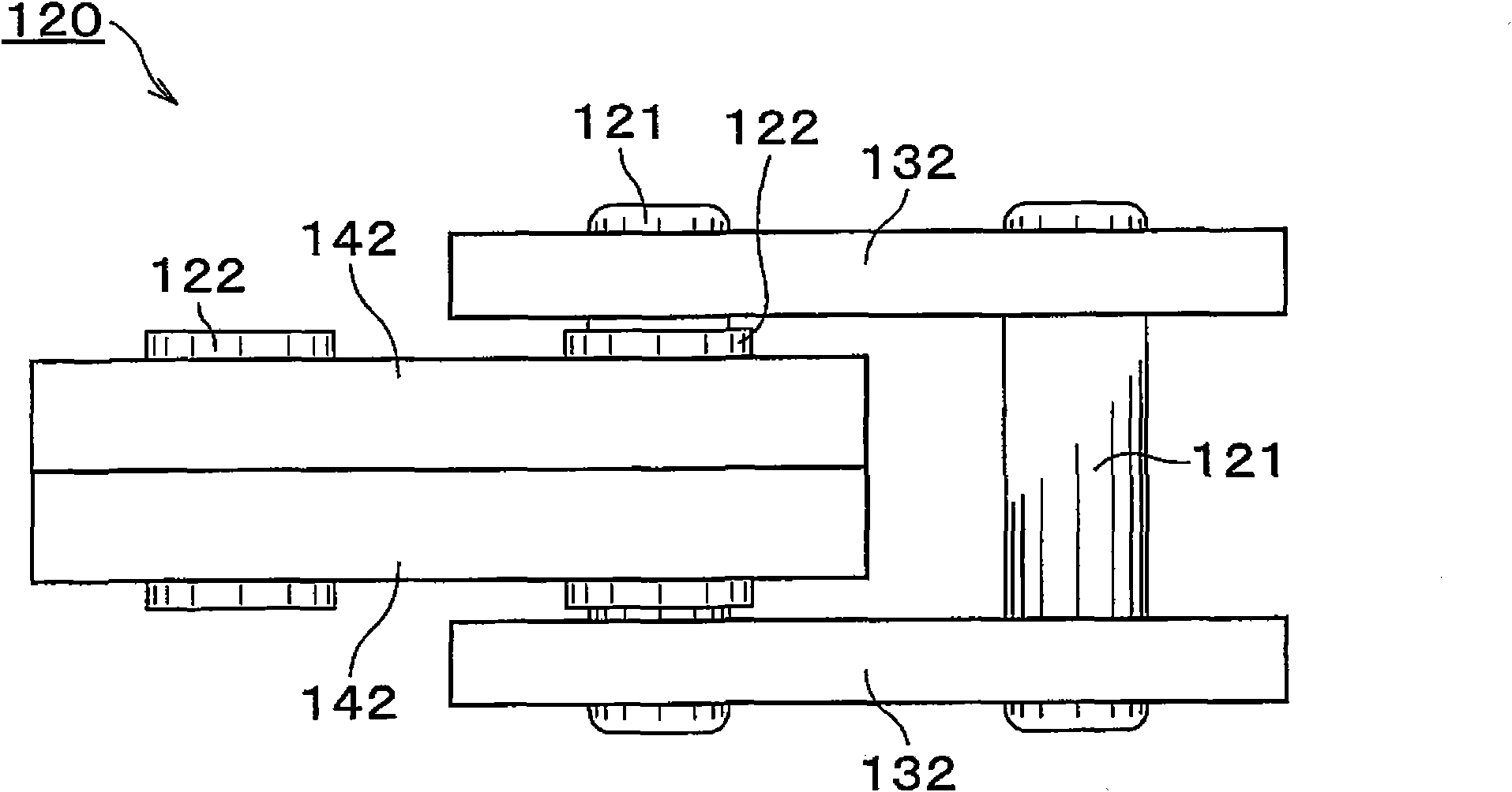
[0090] Such as image 3 , Figure 4 As shown, the chain 120 is composed of a first chain link row, that is, an outer chain link row, and a second chain link row, that is, an inner chain link row. The above-mentioned second link row is constituted by a pair of inner link plates 142 having a pair of front and rear sleeve holes 1...

Embodiment 2

[0097] For the silent chain drive 220 as the second embodiment of the present invention, as Figure 5 As shown, the hollow cylindrical bushing 222 is press-fitted into the bushing hole 243 of the inner link plate 242, and the pair of inner link plates 242 are spaced apart from each other.

[0098] Other structures of the silent chain transmission are the same as those of the first embodiment.

[0099] Therefore, by ensuring the sliding area of ​​the connecting pin 221 and the bushing 222 and reducing the surface pressure, the bending resistance can be reduced to reduce noise and vibration, and it is not necessary to provide too many link plates, and it is not necessary to install the chain at the end of the chain 220. The outer side of the outer link plate 132 is provided with a guide plate for preventing disengagement, so the maximum width of the chain 220 can be narrowed, the number of parts can be reduced, and the weight of the chain 220 can be reduced, thereby reducing the...

Embodiment 3

[0101] Such as Image 6 , Figure 7 As shown, the silent chain transmission device 300 as the third embodiment of the present invention is composed of a chain 320 and a sprocket (the same as the first embodiment, not shown), and the chain 320 is composed of an outer chain link row (the first chain link row ) and the inner chain link row (the second chain link row) are alternately connected and knitted by connecting pins 321 to be able to bend, and the sprocket has a sprocket main body with sprocket teeth on the outer peripheral surface and a Lugs to guide the chain.

[0102] The chain 320 is composed of a first chain link row, that is, an outer chain link row, and a second chain link row, that is, an inner chain link row. The second link row consists of an inner link plate 342 having a front and rear pair of pin holes 343 .

[0103] The outer link plate 332 of the outer link row is provided with plate teeth 334, the connecting pin 321 is inserted through the pin hole 133 of...


PUM


Abstract

The object of the invention is to provide a silent chain transmission device which can reduce width of chains, reduce occupying space, reduce abrasion, vibration and noise, reduce number of parts, easily assemble, can lighten weight to improve tracing ability of tracing speed change. The silent chain transmission device rotates in a transmission way by meshing a chain (120) and a chain wheel (110); the chain (120) is formed by alternatively bending a chain link plate (132, 142) provided with plate teeth (134, 144) through a connection pin 9121); the chain wheel (110) is provided with chain wheel teeth (111) at an outer peripheral surface, wherein the plate teeth (134) are arranged in the outermost row of chain link plate (132) at the width direction of the chain (120); and the chain wheel (110) is provided with a pair of flanges (112) that guide the chain by engaging sprocket-engaging teeth on the outermost plates of the chain.

Description

technical field [0001] The invention relates to a silent chain transmission device. The silent chain transmission device has a chain and a sprocket wheel. Slat teeth are arranged on the link plate of the chain, and sprocket teeth are arranged on the outer peripheral surface of the sprocket wheel. Gear tooth meshing to transmit rotation, for example, relates to a silent chain transmission suitable for a timing system in which a sprocket wound endlessly around a crankshaft and a camshaft respectively provided in the engine compartment is used The silent chain between them drives rotation from the crankshaft to the camshaft. Background technique [0002] Conventionally, there is known a silent chain transmission device which has a chain and a sprocket, and the chain is composed of a first chain link row and a second chain link row alternately connected in a bendable manner by connecting pins, In addition, plate teeth are provided on a part of the link plates or all of the link...

Claims


Application Information

Patent Timeline
Patent Type & Authority Applications(China)
IPC IPC(8): F16G13/04F01L1/348
CPCF01L1/053F01L1/022F01L1/02F16H7/06F16G13/04
Inventor 小乡敏孝
Owner TSUBAKIMOTO CHAIN CO
Learn More