
Ship propeller

A technology for propellers and ships, applied in ship propulsion, propulsion parts, ship parts, etc., can solve the problems of the large volume of the steam boiler, the cooling problem of the combustion chamber, the heat loss of the combustion pipeline, etc. The effect of volume and weight reduction

Inactive Publication Date: 2010-12-29
李江平 +1
View PDF2 Cites 14 Cited by
  • Summary
  • Abstract
  • Description
  • Claims
  • Application Information

AI Technical Summary

Problems solved by technology

A marine jet propulsion disclosed in Chinese Patent (Patent No. 93201592.1) places a hemispherical combustion chamber on the water surface, and obliquely extends into the water through a hollow cylindrical combustion pipe, where the high-temperature and high-pressure airflow interacts with the water to generate thrust However, the high-temperature and high-pressure airflow will quickly emerge from the water and cannot be effectively transformed into changes in the momentum of the water body. In addition, this patent also has problems such as cooling of the combustion chamber and heat loss of the combustion pipeline.
Chinese patent (patent number ZL 200420105265.X) discloses a steam-powered ship propeller, the propeller barrel is connected to the steam pipe of the steam boiler, and high-pressure steam is used to directly do work; however, the steam boiler has problems such as large volume and low thermal efficiency
But it will be very uneconomical to make the speed of ordinary ships reach more than 80kn

Method used


Image

  • Ship propeller
  • Ship propeller
  • Ship propeller

Examples


Embodiment Construction

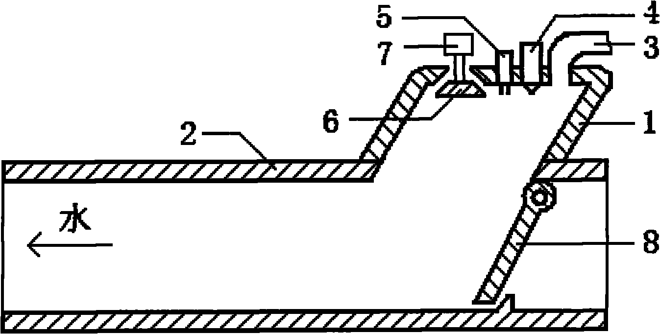
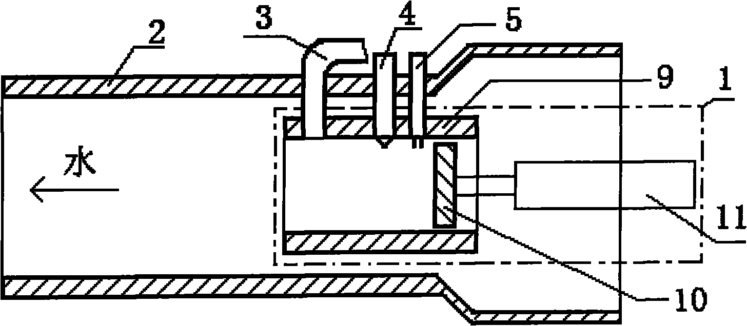
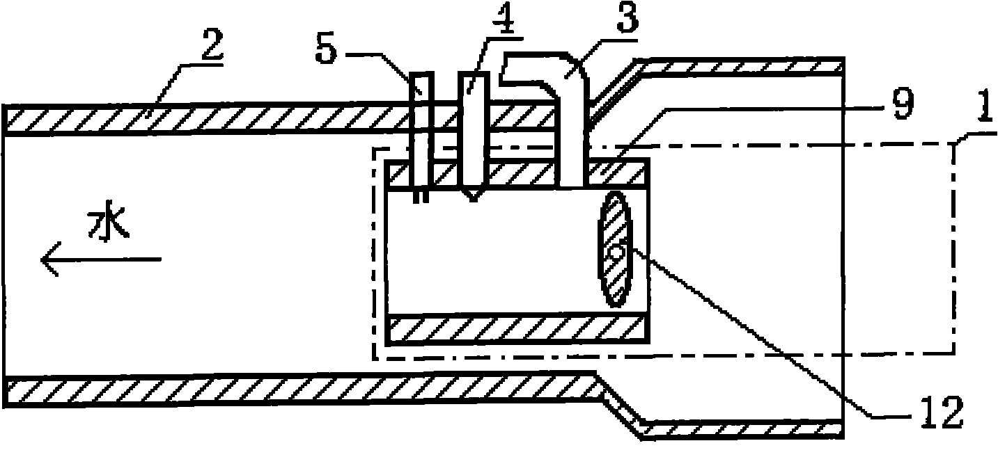
[0036] figure 1 The ship propeller shown is mainly composed of a cylinder 1 and a nozzle 2, the nozzle is connected to the lower end of the cylinder, the top of the cylinder is provided with a compressed air inlet 3, a fuel nozzle 4, an ignition device 5 and an exhaust valve 6, and the nozzle is provided with Swing check valve 8.

[0037] exist figure 1 In the specific embodiment shown, both the cylinder and the nozzle work in water, and the nozzle should be in a substantially horizontal state during installation, and the cylinder is located at the top of the nozzle; before the work, the cylinder and the nozzle are filled with water; Air valve 6, and fill the cylinder with fresh air through the cylinder compressed air inlet 3, and inject an appropriate amount of fuel into the cylinder at the same time, the fuel nozzle 4 should have an atomization function, so that the air and fuel can be fully mixed and meet the explosion requirements; After inflation and fuel injection, und...


PUM


Abstract

The invention discloses a ship propeller which mainly comprises a cylinder and a jet pipe, wherein the cylinder is provided with a compressed air inlet, a fuel nozzle and an ignition unit. The ship propeller is characterized in that both the cylinder (1) and the jet pipe (2) of the propeller work in water, compressed air and fuel are respectively introduced into the cylinder through the compressed air inlet (3) and the fuel nozzle (4) and are subject to burning explosion under the action of an ignition unit (5), and burning explosion products directly jet out a water column in the jet pipe (2) so as to generate a thrust force based on the reactive force. Compared with the known ship propelling system, the propeller uses the cylinder part as the power unit, uses the jet pipe part as the propelling unit and realizes the integration of the power unit and the propelling unit, thereby having the advantages of high propelling efficiency, high energy utilization efficiency, high economical efficiency, simple structure and high operational reliability. The invention includes multiple implementation schemes, can realize the ultra high-power propulsion by modular combination and is applicable to various ships.

Description

technical field [0001] The invention relates to a propulsion device of a ship, in particular to a ship propeller technology with a new structure. Background technique [0002] Known ship propulsion systems, from the perspective of power devices, mainly include internal combustion power devices, steam power devices, nuclear power devices, fuel cells, etc., and internal combustion power devices include diesel engines, gasoline engines and gas turbines, etc.; Type gearbox and drive shaft, generator, power transformation and distribution, and motor system; from the perspective of propulsion devices, there are mainly propeller propellers, water jet propellers, straight wing propellers, paddle wheel propellers, etc. [0003] From the analysis of propulsion efficiency and energy utilization rate, the propulsion efficiency and energy utilization rate of the existing ship propulsion system are relatively low. The main reason is that the system composed of power device, transmission d...

Claims


Application Information

Patent Timeline
Patent Type & Authority Applications(China)
IPC IPC(8): B63H11/02
Inventor 李江平杜冬妮
Owner 李江平
Learn More