Pellet resistor with multi-cascade attenuator circuit

A technology of attenuating circuits and chip resistors, applied in circuits, electrical components, waveguide-type devices, etc., can solve the problems of narrow operating frequency band, increase of third-order intermodulation impurities, large reflection loss, etc., to avoid local thermal shock, The effect of good index consistency and high working frequency band

Inactive Publication Date: 2010-12-15
合肥佰特微波技术有限公司
View PDF3 Cites 11 Cited by
  • Summary
  • Abstract
  • Description
  • Claims
  • Application Information

AI Technical Summary

Problems solved by technology

[0003] This working principle has the following four disadvantages: First, because the signal power is directly transmitted to the resistor 7 through the external lead wire and the cavity, that is, the transmission route of the whole machine is from the coaxial structure to the microstrip line structure, and finally reaches the resistor 7. As a result, its working frequency band is narrow and the reflection loss is large; the second is that all the energy of the signal power is absorbed by the resistor 7 at one time, causing the resistor 7 to heat up sharply in a short period of time, which can easily cause the resistor 7 to spark, resulting in the scrapping of the whole machine , which seriously affects the service life and quality of use of the entire system; the third is that the part where the resistor 7 is connected to the grounding microstrip 4 and the central conductive strip 3 is at a right angle and has not been processed by a parabolic gradient, resulting in a third-order signal power generated here. The increase of intermodulation impurities will have a greater negative impact on the third-order intermodulation performance of the whole machine; Fourth, no matter whether the external leads or the cavity and the connector of the resistor must be welded, and the solder joints The size, shape, length of welding time, etc. will have a certain negative impact on the performance and indicators of the product, resulting in extremely poor consistency in the performance indicators of the whole machine

Method used


Image

  • Pellet resistor with multi-cascade attenuator circuit
  • Pellet resistor with multi-cascade attenuator circuit
  • Pellet resistor with multi-cascade attenuator circuit

Examples


Embodiment

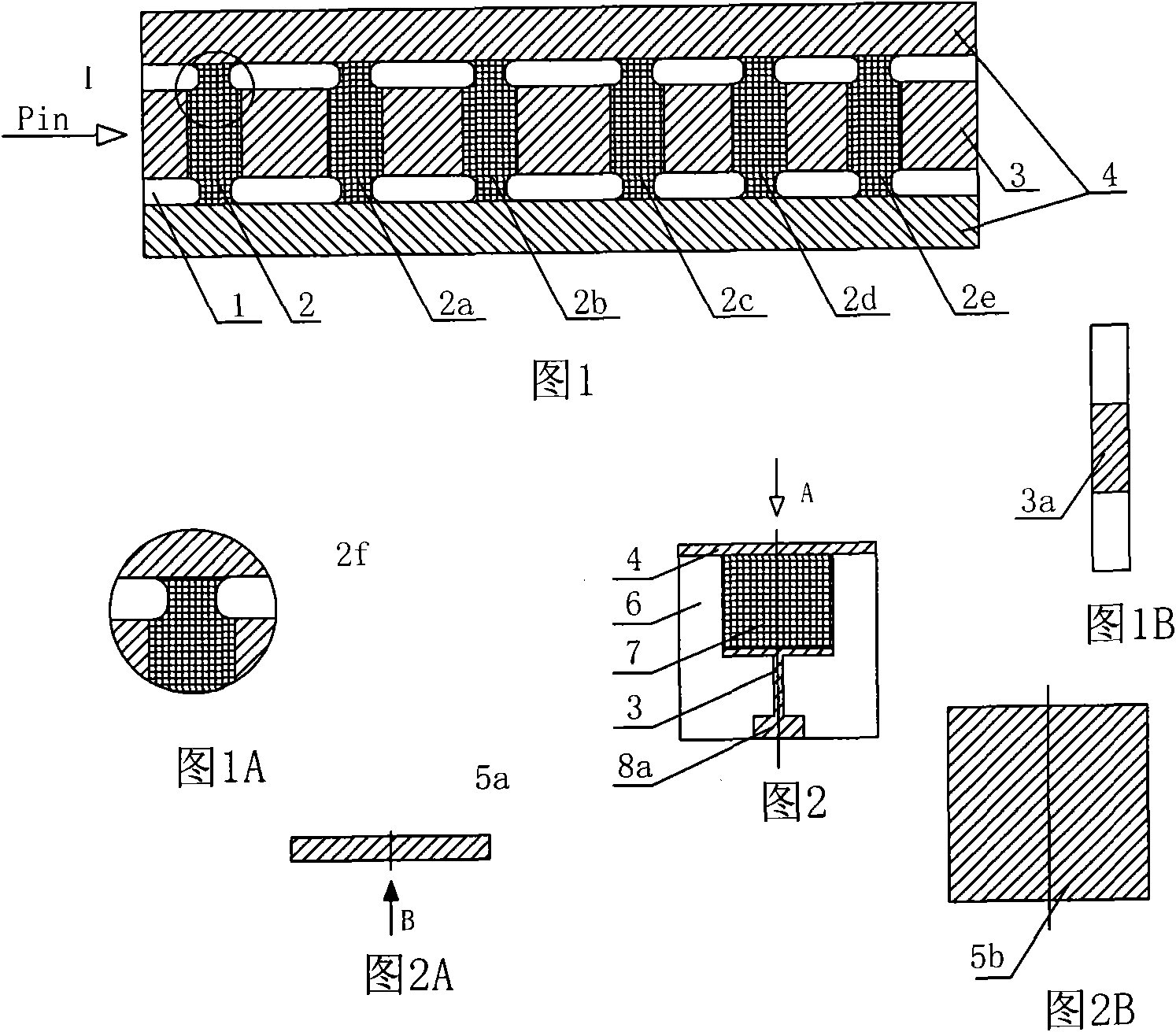
[0016] Embodiment: In this embodiment, chip resistors with multi-cascade attenuation circuits are provided with attenuation resistors 2, 2a, 2b, 2c, and 2d whose attenuation degree increases successively on the rectangular substrate 1 along its length direction from the input end to the terminal interval. , 2e, wherein the attenuation resistor 2e closest to the substrate terminal is a matching terminal capable of completely absorbing the remaining signal power. The attenuation resistors are connected with the central conduction band 3 provided on the substrate, the two sides of the substrate 1 are provided with grounding microstrips 4, and the two ends of the substrate are provided with end faces communicated with the central conduction band Electrode 3a.

[0017] combine Figure 1A , the grounding microstrip 4, the central conduction strip 3 and each attenuation resistor are transitionally connected with an arc-shaped intermodulation angle 2f. The principle characteristics ...


PUM


Abstract

The invention discloses a pellet resistor with a multi-cascade attenuator circuit. Attenuator resistors with sequentially increasing attenuation degree are arranged on a rectangular base plate along the length direction from the input end to the terminal, and are connected by center guide belts arranged on the base plate, two side parts of the base plate are provided with grounding micro strips, and two end parts of the base plate are provided with end face electrodes communicated with the center guide belts. Though practical verification, the product assembled by the pellet resistor with the multi-cascade attenuator circuit has indexes of meeting working frequency of DC-18GHz, standing-wave ratio Vser of not more than 1.15 and three-order intermodulation IM3 of not more than -130dbc@2X+43dbm through practical tests.

Description

Technical field: [0001] The invention relates to an electromagnetic wave power level absorbing device, specifically a chip resistor with multi-cascade attenuation circuits, which belongs to products used in microwave fields such as communication, scientific research, and testing. Background technique: [0002] At present, with the increase of communication terminal users and the advancement of science and technology, higher requirements are placed on the ability of the network to transmit data, signal power compatibility, and anti-interference, which makes the working frequency band, power capacity, and reflection loss of microwave coaxial devices , third-order intermodulation, mechanical stability and other performance requirements are getting higher and higher. However, the third-order intermodulation index of microwave coaxial devices is poor at this stage, the reflection loss is large, and the mechanical stability is low. like figure 2 Shown is an ordinary single-stage...

Claims


Application Information

Patent Timeline
IPC IPC(8): H01P1/22
Inventor 齐磊张祝松
Owner 合肥佰特微波技术有限公司
Why Eureka
Try Eureka