
Method and device for sterilizing/washing cap

A cleaning device and cleaning medium technology, applied in packaging sterilization, bottle cap pretreatment, chemistry, etc., can solve problems such as poor cleaning efficiency, save space and prevent deformation

Inactive Publication Date: 2010-12-08
TOYO SEIKAN KAISHA LTD
View PDF3 Cites 3 Cited by
  • Summary
  • Abstract
  • Description
  • Claims
  • Application Information

AI Technical Summary

Problems solved by technology

[0009] (2) For sterilization and cleaning, since hot water or sterile water is sprayed from the upstream side to the downstream side to the cover in the downwardly inclined tank, it becomes dirty hot water or sterile water sprayed from the upstream side The cleaning efficiency is poor due to continuous spraying of new sterile water on the downstream side while moving together with the cap and remaining attached to the cap sufficiently

Method used


Image

  • Method and device for sterilizing/washing cap
  • Method and device for sterilizing/washing cap
  • Method and device for sterilizing/washing cap

Examples


Embodiment 1

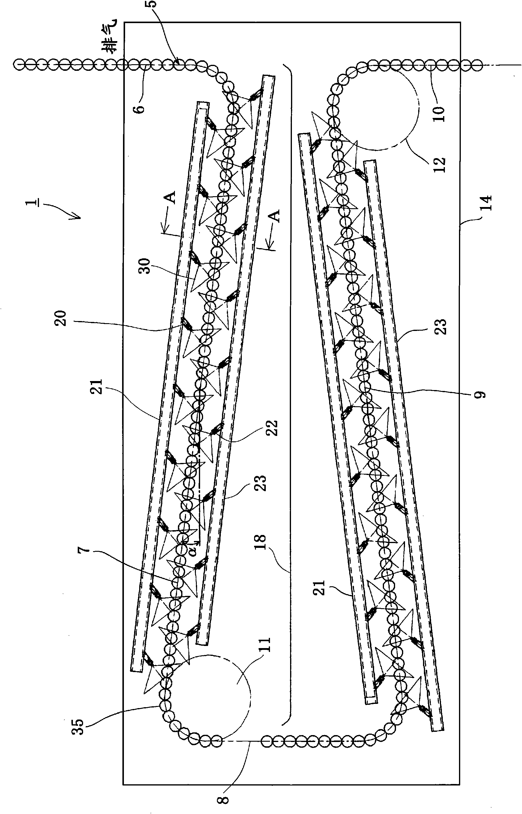
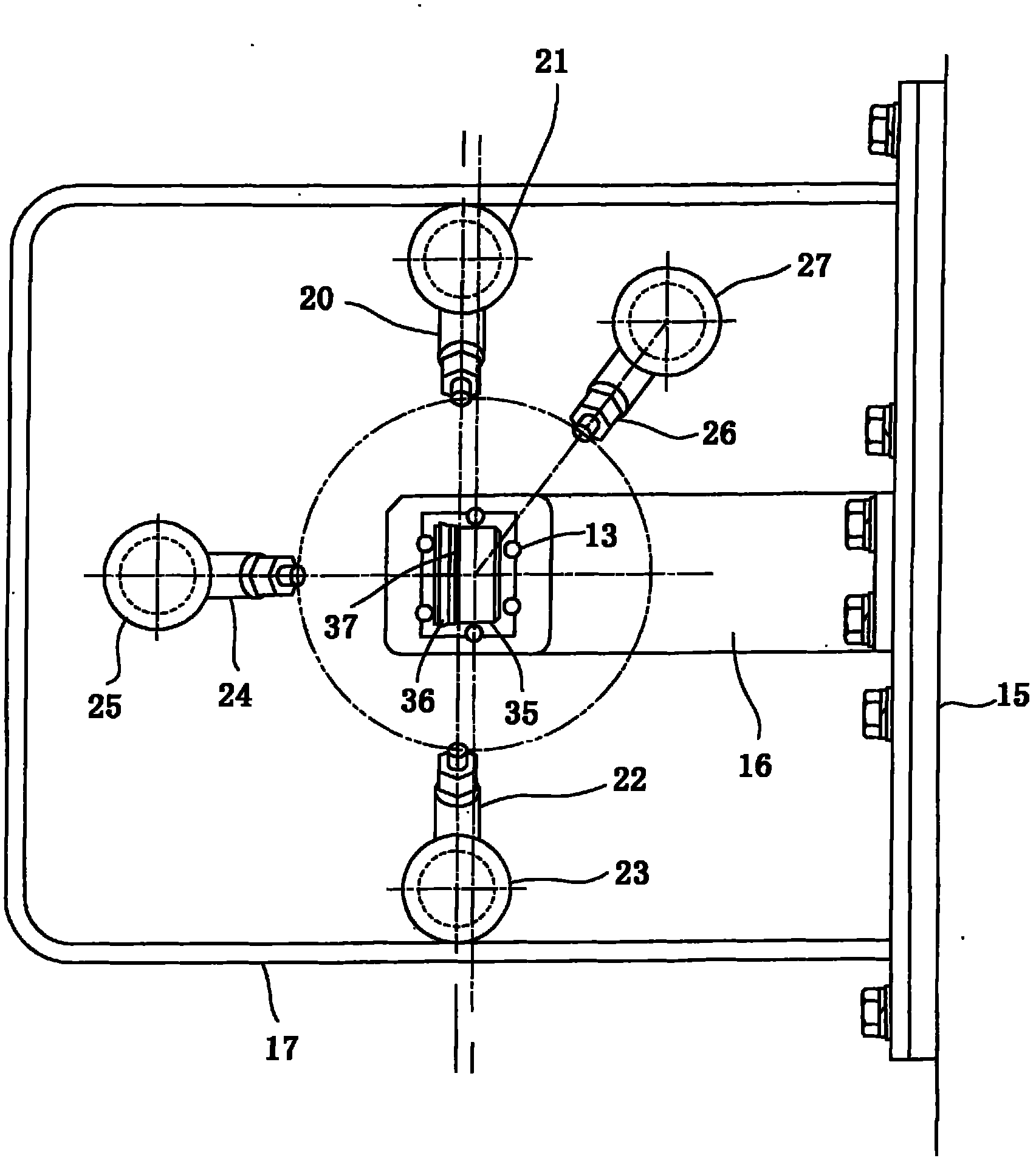
[0045] Set the inclination angle of the rising inclined groove part to 7° to form a groove, and surround the groove with Figure 4 In the arrangement form shown, hot water pipes A to D are arranged. These hot water pipes A, B, C, and D are formed so that a maximum of 14 nozzles can be arranged over the entire length based on a pitch of 100 mm (the length of the nozzle section is 1400 mm), and each part is arranged from the upstream in the state shown in Table 1. Configure jet nozzles. Among them, in the table, F represents a fan nozzle (spray angle 110°), S represents a straight nozzle (spray angle 0°), and P represents a plug (that is, there is no nozzle but a closed state). Such as Figure 5 As shown, each of the above-mentioned nozzles is arranged at an inclination of 45° relative to the conveying direction. in addition, Figure 4 In a1, b1, c1, d1 represent the linear distance from the outer periphery of each hot water pipe to the nearest linear guide of the groove, an...

Embodiment 2

[0054] As Example 2, such as Figure 6 As shown, all spray nozzles of the hot water pipe A are arranged at right angles to the conveying direction. In this case, the total number of spray nozzles having an inclination angle of 90° is seven, accounting for about 21% of the total number of 33 spray nozzles. In this case, the injection pressure of the hot water sprayed from the injection nozzles arranged in the hot water pipe A at right angles to the conveyance direction acts on the caps, which becomes conveyance resistance, and creates a distance between the caps being conveyed. As a result, the shielding portion that hot water cannot touch disappears, hot water can effectively contact the entire circumference of the cover, and the cleaning effect is further improved compared to the case of Example 1. Therefore, the orientation of the nozzles is not limited to the case where all the nozzles are arranged obliquely with respect to the conveying direction of the caps. By providin...


PUM


Abstract

A chute type sterilizing / washing device for a cap, in which deformation of a cap is prevented by relaxing pressure accumulation acting on a synthetic resin cap in the chute, and sterilization and washing can be carried out efficiently by reducing the impact of hot water or germ free water jetted at the upstream side on the hot water or germ free water at the upstream side. The chute (5) has ascending chute portions (7, 9), a hot water pipe having a plurality of nozzles for jetting hot water as a sterilizing / washing medium is arranged along the ascending chute portion, hot water is jetted to a cap fed to the ascending chute portion, the cap (35) receives a thrust for ascending the ascending shoot portion by the jet pressure of the hot water thus sterilizing and washing the cap with the sterilizing / washing medium.

Description

technical field [0001] The present invention relates to a method and device for sterilizing and cleaning caps, and more particularly to a chute-type method and device for sterilizing and cleaning caps suitable for sterilizing and cleaning while transporting synthetic resin caps through a chute. Background technique [0002] Conventionally, when assembling synthetic resin caps to bottle containers filled with contents such as soft drinks, it was often necessary to provide cap sterilization and cleaning steps before supplying the caps to a capper. As the method of sterilization and cleaning of the cap in this case, the following cases are generally known: the case where the cap is sterilized and cleaned by conveying the cap by its own weight while utilizing a tank (for example, refer to Patent Document 1); In the case of being transported by a rotating turntable or a roller-type star wheel (star wheel), etc., while carrying out sterilization and cleaning (for example, refer to...

Claims


Application Information

Patent Timeline
IPC IPC(8): B65B55/04B65B55/06
CPCA61L2/07A61L2/16A61L2/04A61L2/18B67B3/003B65B55/10
Inventor 上田信幸上原智史小南宪一须田悠介
Owner TOYO SEIKAN KAISHA LTD
Learn More