


Quick Research
Generate reliable direction feasibility study reports for your R&D in just a few steps.

Technical Q&A
Discover and master advanced knowledge NOW. Basics, ideas, possibilities, all at once.

Find Solutions
As an expert in R&D theories, this can generate solutions to your technical problems instantly.

Evaluate Feasibility
Analyze your overall solution with one click, know your potential R&D risks in advance.

Monitor Landscape
Get weekly tech updates, stay abreast of the latest tech innovations and key insights.
Gas liquefying and circulating structure
A cycle structure and gas technology, applied in the field of gas liquefaction cycle structure, can solve the problems of high investment cost and operation cost of pretreatment device, and achieve the effects of simple structure, cost reduction and compact system
- Summary
- Abstract
- Description
- Claims
- Application Information
AI Technical Summary
Problems solved by technology
Method used
Image

Examples
Embodiment 1
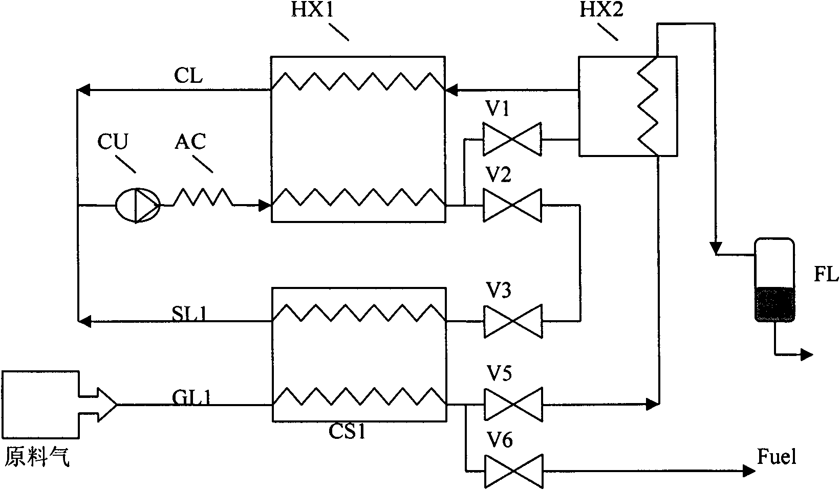
[0037] Embodiment 1: Use the gas liquefaction cycle structure provided by the present invention to liquefy natural gas.
[0038] Such as figure 1 As shown, the gas liquefaction cycle structure in Embodiment 1 includes compressor unit CU, cooler AC, main heat exchanger HX1, latent heat exchanger HX2, first sensible heat exchanger CS1, LNG storage tank FL, main Throttle refrigeration element V1, auxiliary throttle refrigeration element V2, first refrigeration control valve V3, first raw material control valve V5, first regeneration control valve V6 and pipelines; the connection method is: the outlet of the compressor unit CU is connected to the cooler AC inlet and AC outlet of the cooler are connected to the high-pressure inlet of the main heat exchanger HX1, and the high-pressure outlet of the main heat exchanger HX1 is respectively connected to the inlet of the main throttling refrigeration element V1 and the inlet of the auxiliary throttling refrigeration element V2 through a...
Embodiment 2
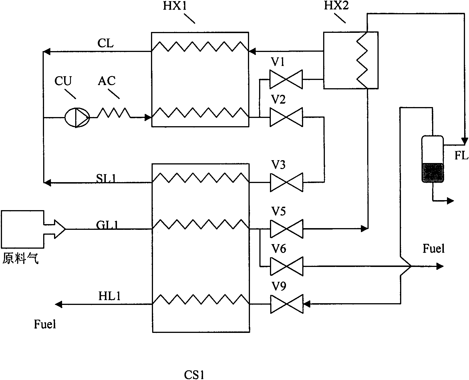
[0040] Embodiment 2: use the gas liquefaction cycle structure provided by the present invention to liquefy natural gas.
[0041] Such as figure 2 The gas liquefaction circulation structure shown, in addition to the circuits and original components listed in Example 1, also includes a first gas circuit HL1; the first gas circuit HL1 is controlled by the LNG storage tank FL, the first return flow Valve V9, the first sensible heat exchanger CS1 and pipelines; the connection method is: the low-temperature gas in the LNG storage tank FL is connected to the inlet of the first return control valve V9 by the pipeline, and the outlet of the first return control valve V9 is connected to the first The gas return inlet of the sensible heat exchanger CS1, and the gas return outlet of the first sensible heat exchanger CS1 are used as the return gas fuel outlet. When the refrigerator is working, the natural gas is firstly cooled by the first sensible heat exchanger CS1 and further purified...
Embodiment 3
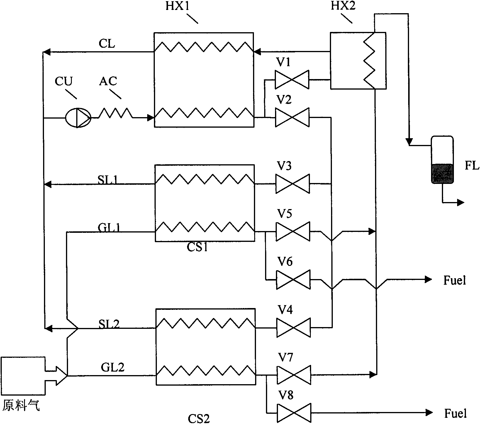
[0042] Embodiment 3: Coal bed gas is liquefied using a gas liquefaction cycle structure provided by the present invention.
[0043] Such as image 3 The gas liquefaction cycle structure shown, in addition to the circuits and components listed in Embodiment 1, also includes a second refrigeration circuit SL2 and a second raw gas pipeline GL2. The second refrigeration circuit SL2 is composed of compressor unit CU, cooler AC, main heat exchanger HX1, auxiliary throttling refrigeration element V2, second refrigeration control valve V4, second sensible heat exchanger CS2 and pipelines ; The connection method is: the outlet of the auxiliary throttling refrigeration element V2 is connected to the inlet of the second refrigeration control valve V4, the outlet of the second refrigeration control valve V4 is connected to the refrigerant inlet of the second sensible heat exchanger CS2, and the second sensible heat exchanger CS2 The outlet of the refrigerant is connected to the inlet of ...
PUM
 Abstract
Description
Claims
Application Information
 - R&D Engineer
- R&D Manager
- IP Professional
- Industry Leading Data Capabilities
- Powerful AI technology
- Patent DNA Extraction
Browse by: Latest US Patents, China's latest patents, Technical Efficacy Thesaurus, Application Domain, Technology Topic, Popular Technical Reports.
© 2024 PatSnap. All rights reserved.Legal|Privacy policy|Modern Slavery Act Transparency Statement|Sitemap|About US| Contact US: help@patsnap.com