Injection molding machine for bimaterial molding and method of controlling same
An injection molding machine and dual-material technology, which is applied to the injection molding machine for dual-material molding and its control field, can solve the problems of difficult to rotate the central axis, difficult to replace the mold, sticking of the bearing part, etc., so as to avoid collision and prevent the mold from being damaged. Effect
- Summary
- Abstract
- Description
- Claims
- Application Information
AI Technical Summary
Problems solved by technology
Method used
Image
Examples
no. 1 approach
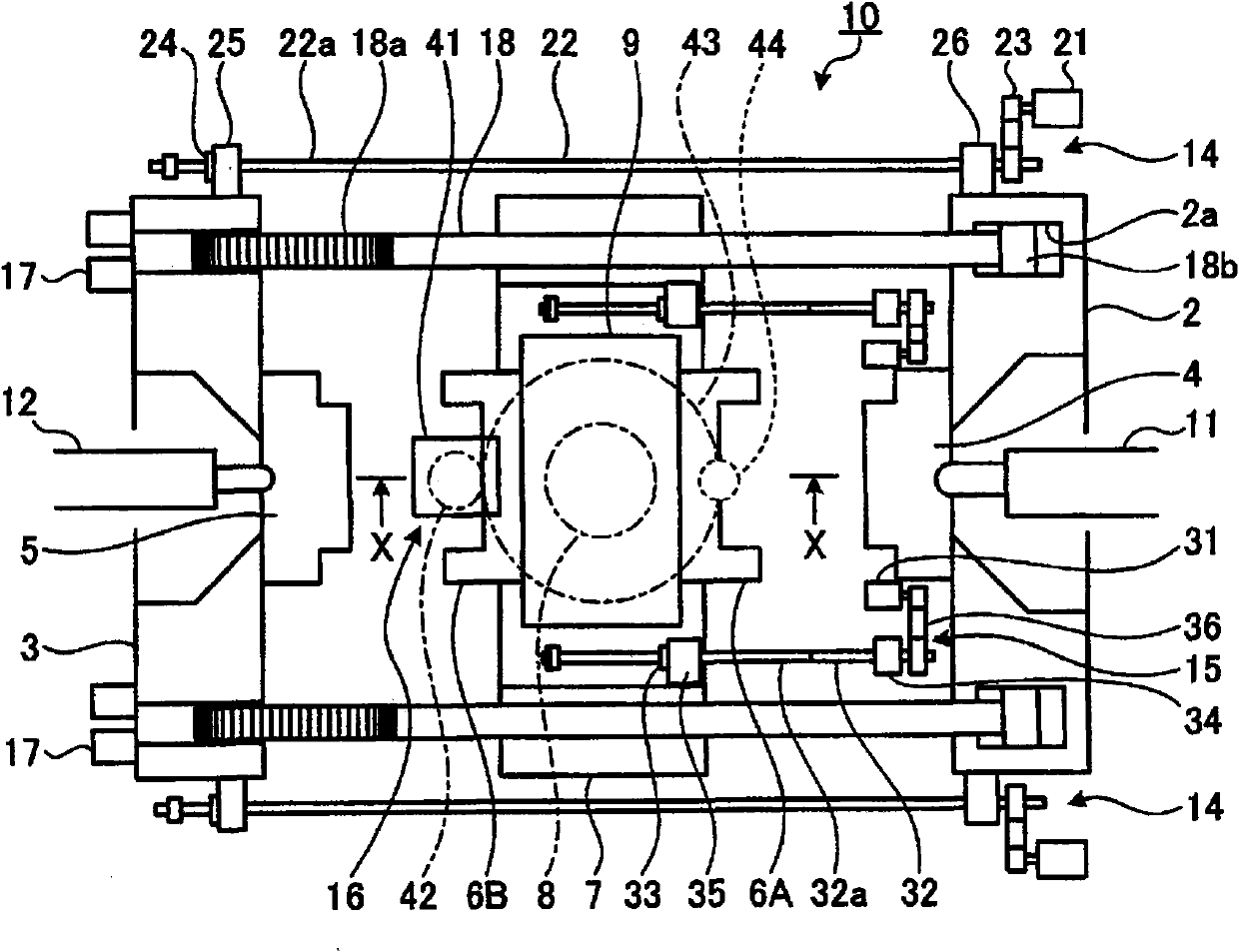
[0075] The injection molding machine for bi-material molding of this embodiment has two cavities formed by a mold for a movable platen, a mold for a fixed platen, and a mold provided on both sides of the rotary platen between the two platens. Different types of resins are injected separately, double injection is performed by rotating the rotary die plate 180 degrees, and the two materials are integrally molded. Among them, it is easy to set the movement of the movable die plate and the rotary die plate, and the drive of the rotation of the rotary die plate. Controlled electric drive unit.
[0076] Next, the first embodiment will be described with reference to the drawings.
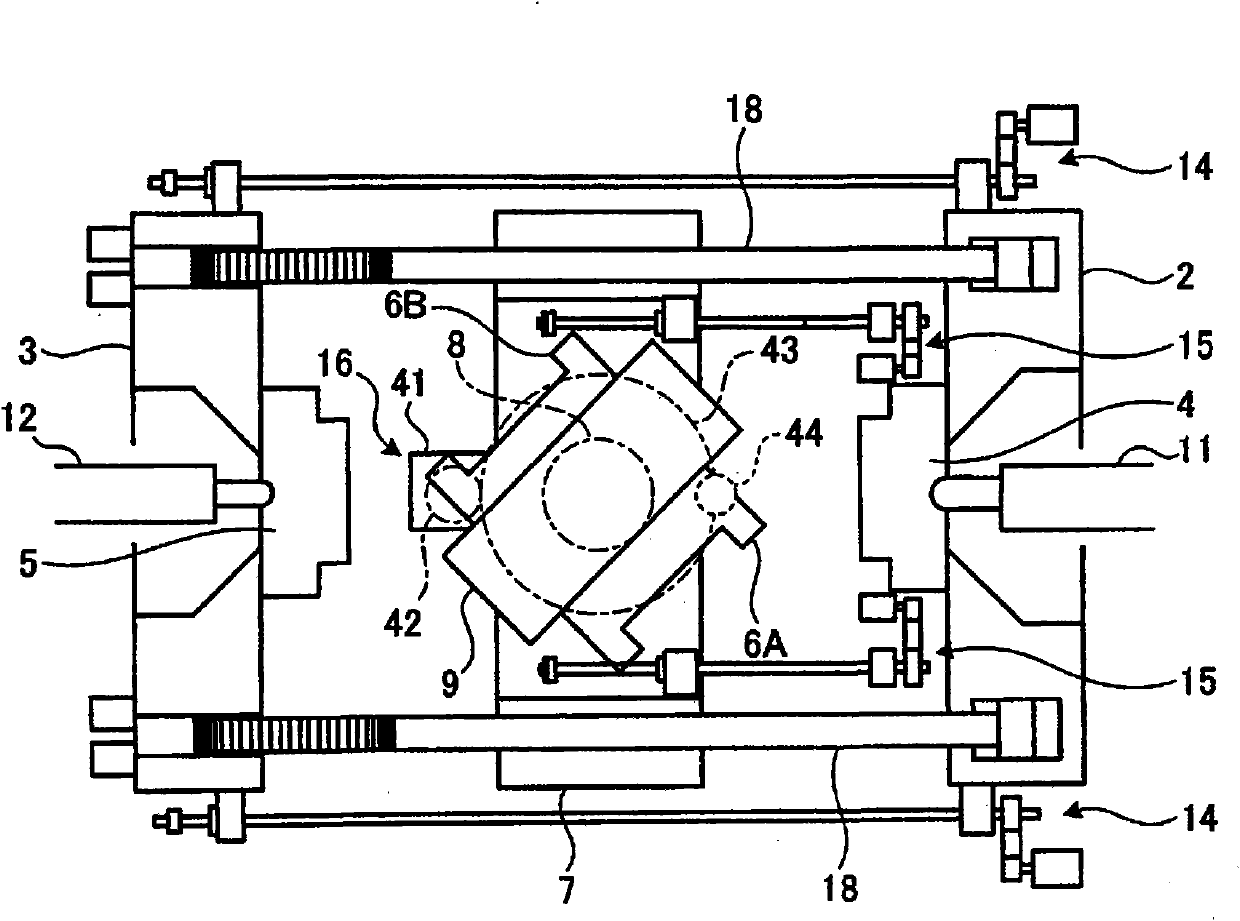
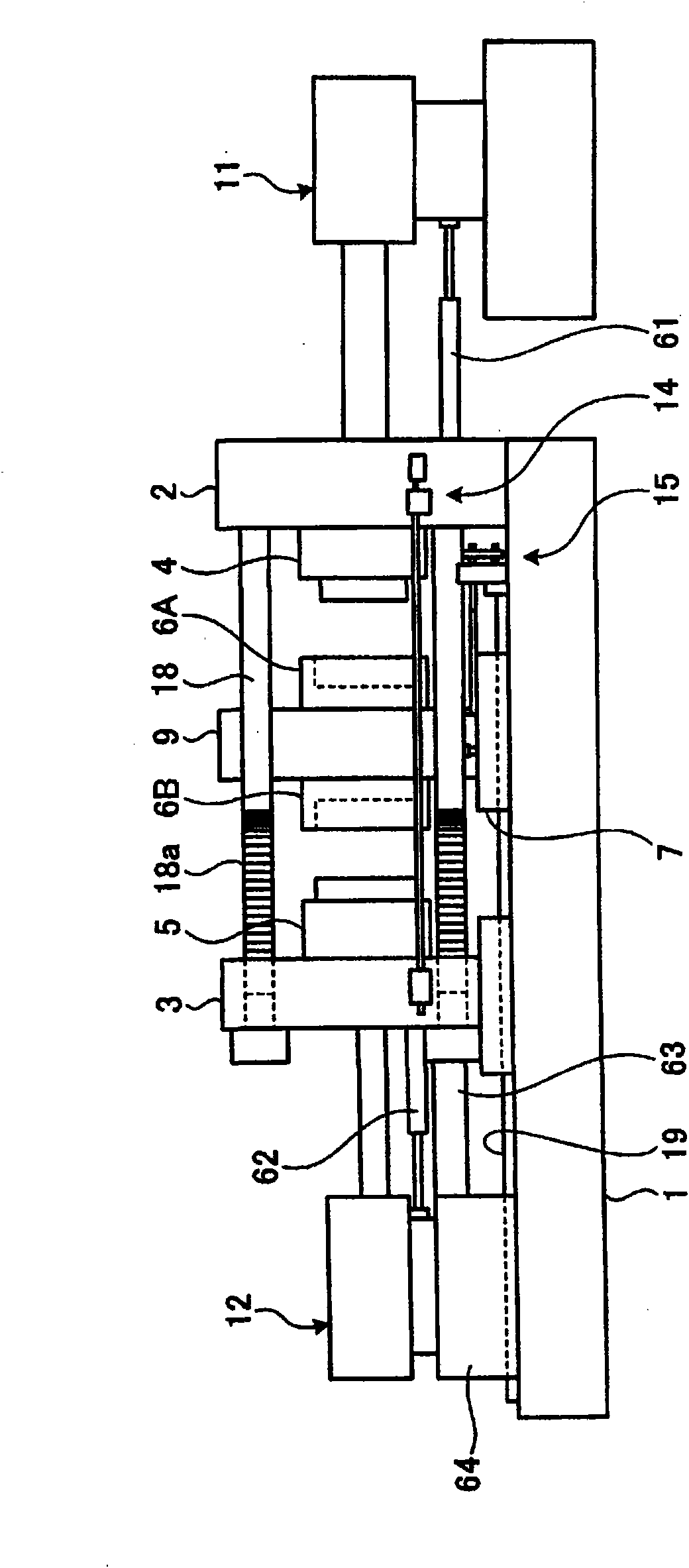
[0077] figure 1 This is a schematic plan view of the injection molding machine for dual-material molding of the present invention. figure 2 is to indicate figure 1 Diagram of the rotation action of the rotary die plate of the injection molding machine for bi-material molding. image 3 Yes figure 1 Si...
no. 2 approach
[0131] Next, a second embodiment of the present invention will be described. The difference between the second embodiment and the first embodiment is as follows: Figure 7 As shown in the schematic plan view of the injection molding machine 30 for bi-material molding, the reversing table 7 is provided with a servo motor A ( 21 ) and a ball screw for driving the movable platen opening and closing unit 46 of the movable platen 3 . The rest of the support base 26 of the lever shaft 47 is the same as that of the first embodiment, so the description of other structures is omitted.
[0132] The advantage of this second embodiment is that the ball screw shaft 47 can be shortened, so that the critical speed of the ball screw shaft 4 can be increased, and the opening and closing speed of the movable die plate 3 can be increased. In addition, since the ball screw is directly connected between the rotary die plate 9 and the movable die plate 3, it is not necessary to detect and control ...
no. 3 approach
[0134] Next, a third embodiment of the present invention will be described. The difference between the second embodiment and the first embodiment is as follows: Figure 8 As shown in the schematic side view of the rotary table plate, the rotary table plate rotation unit 50 is composed of the servo motor C ( 41 ) mounted on the reversing table 7 , the pinion gear 53 mounted on the servo motor C ( 41 ), and the pinion gear 53 The meshing rotary plate 9 is integrally provided with a large gear 52 and an annular toothed belt 54 wound around the pinion 53 and the large gear 52, and is a rotary drive that makes the rotary plate 9 rotate half a circle in the forward and reverse directions. The unit is the same as that of the first embodiment except for this, so the description of other structures is omitted.
[0135] According to the present embodiment, there is an advantage in that it is not necessary to directly abut the large gear 52 and the pinion 53, and the distance between th...
PUM
 Abstract
Description
Claims
Application Information
 - R&D Engineer
- R&D Manager
- IP Professional
- Industry Leading Data Capabilities
- Powerful AI technology
- Patent DNA Extraction
Browse by: Latest US Patents, China's latest patents, Technical Efficacy Thesaurus, Application Domain, Technology Topic, Popular Technical Reports.
© 2024 PatSnap. All rights reserved.Legal|Privacy policy|Modern Slavery Act Transparency Statement|Sitemap|About US| Contact US: help@patsnap.com


