
System and method for recovering waste heat of continuous hot steel slag

A waste heat recovery system and technology of hot steel slag, applied in the field of waste heat recovery, can solve the problems of low energy consumption heat recovery process of hot steel slag, high fluidity requirements of steel slag, low heat recovery rate and service life, etc., to achieve continuous and stable recovery of heat, Adjustable steel slag conveying volume and the effect of processing volume control

Inactive Publication Date: 2010-11-10
SHOUGANG CORPORATION
View PDF8 Cites 11 Cited by
  • Summary
  • Abstract
  • Description
  • Claims
  • Application Information

AI Technical Summary

Problems solved by technology

But with this method, the thin slag sticks to the drum and must be smashed off with a rake, the heat recovery rate and service life of the equipment are low, and the obtained slag is in the form of flakes, which is not easy to use
[0006] In summary, the existing waste heat recovery systems and processes have problems such as high energy consumption, high requirements on the fluidity of steel slag, and low heat recovery efficiency, and it is difficult to process steel slag on a large scale
At present, there is no waste heat recovery process for hot steel slag with low energy consumption and adaptable to different fluidity

Method used


Image

  • System and method for recovering waste heat of continuous hot steel slag
  • System and method for recovering waste heat of continuous hot steel slag
  • System and method for recovering waste heat of continuous hot steel slag

Examples


Embodiment Construction

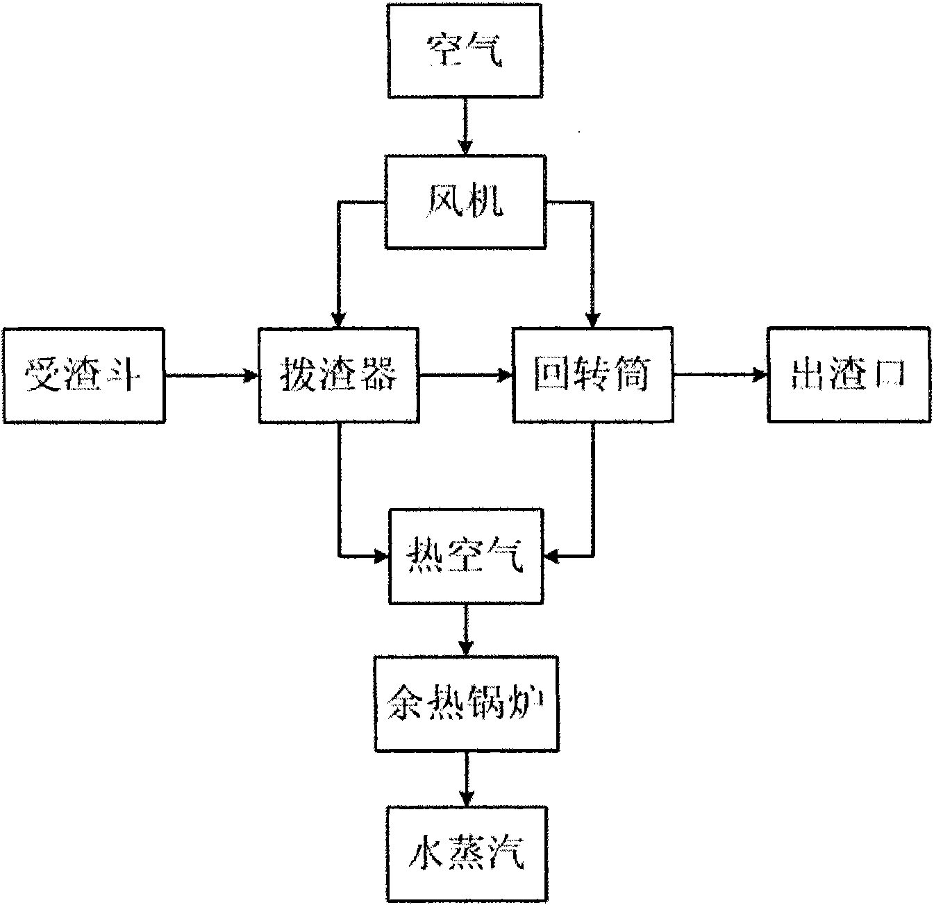
[0028] like figure 1 As shown in the figure, the steel slag dumped from the slag tank with a temperature higher than 1500 ℃ enters the slag removal device from the slag receiving hopper, and is continuously conveyed in the slag removal device and transported to the rotary drum. At the same time, air is blown into the slag removal device and the rotary drum through the fan to achieve secondary heat exchange with the steel slag, so that the steel slag is lowered to below 700°C and 300°C respectively, the air is heated and converted into hot air, and water is generated through the waste heat boiler. The steam is used for energy utilization, and the heat exchange is transformed into a cold state and the steel slag broken by the rotary drum is discharged from the slag outlet.

[0029] like figure 2 As shown, the key equipment slag removal device in this process system adopts a tunnel structure. The hot steel slag in the slag tank enters the slag removal device through the slag i...


PUM


Abstract

The invention relates to a system and a method for recovering waste heat of continuous hot steel slag, which belong to the technical field of steel-making waste heat recovery. The system comprises a slag-receiving hopper, a slag-poking device, a revolving drum, a fan, a waste heat recovery system and a slag outlet, wherein the slag-poking device has a tunnel type structure and consists of a slag slot, a scraper blade, a chain and a chain wheel; the scraper blade is arranged on the chain; the scraper blade is driven by the chain to move in the slag slot and continuously push the hot steel slag to the revolving drum; slag-disintegrating teeth and a material-lifting plate are distributed on the inner wall of the revolving drum; and the steel slag exchanges heat with circulate air conveyed by the fan in the whole dynamically conveying process to generate high-temperature air flow. The system and the method have the advantages of suitability for a steel slag waste heat recovery process, high adaptability to the mobility of the steel slag, high steel slag processing capacity, easy control, continuous and stable heat recovery and capacity of disintegrating large blocks of the steel slag into small blocks which are convenient to recycle.

Description

technical field [0001] The invention belongs to the technical field of waste heat recovery, and in particular relates to a waste heat recovery system and method for hot steel slag, which is suitable for waste heat recovery of steel slag with various fluidities generated in the steelmaking process. Background technique [0002] The recovery and efficient conversion of waste heat resources in iron and steel enterprises has always been the focus of attention of metallurgical workers all over the world. Among them, a large amount of liquid steel slag produced in the steelmaking process has a temperature of 1500°C to 1700°C, and the quality of the waste heat is high, which is of great use value. At present, domestic and foreign iron and steel enterprises have failed to effectively realize the recycling of sensible heat of steel slag. Most steel mills use open-air slag splashing and water cooling, and some steel mills use shallow pan hot splashing method, stuffy tank method, gran...

Claims


Application Information

Patent Timeline
Patent Type & Authority Applications(China)
IPC IPC(8): C21B3/06F27D17/00
CPCY02P10/20Y02P10/25Y02W30/50
Inventor 廖洪强时朝昆冯向鹏吴朝锋杨护红汤博逸余广炜王荣
Owner SHOUGANG CORPORATION
Learn More