
LED light source module

An LED light source and module technology, applied in the field of LED lighting, can solve the problems affecting the excitation efficiency and life of phosphors, short life of LED light-emitting modules, low light extraction efficiency, etc., and achieves lower temperature, simple structure, and high light extraction efficiency. Effect

Inactive Publication Date: 2010-11-03
中山大学佛山研究院
View PDF5 Cites 21 Cited by
  • Summary
  • Abstract
  • Description
  • Claims
  • Application Information

AI Technical Summary

Problems solved by technology

However, the structure of the existing LED light source module is generally more complicated, and its phosphor layer is generally exposed in the air, so the attenuation of the phosphor is faster, the life of the LED light-emitting module is shorter, and the light extraction efficiency is lower; Although the phosphor powder of a few existing LED light source modules is not exposed to the air, it is usually very close to the LED light-emitting chip, causing the temperature of the phosphor powder to be too high, thereby affecting the excitation efficiency and life of the phosphor powder

Method used


Image

  • LED light source module
  • LED light source module
  • LED light source module

Examples


Embodiment Construction

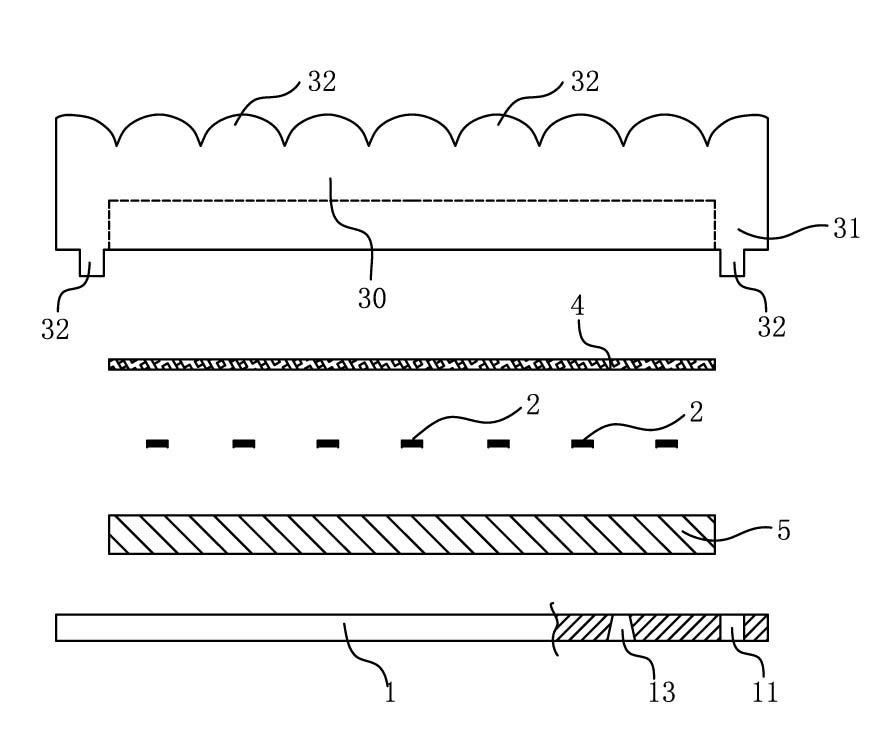
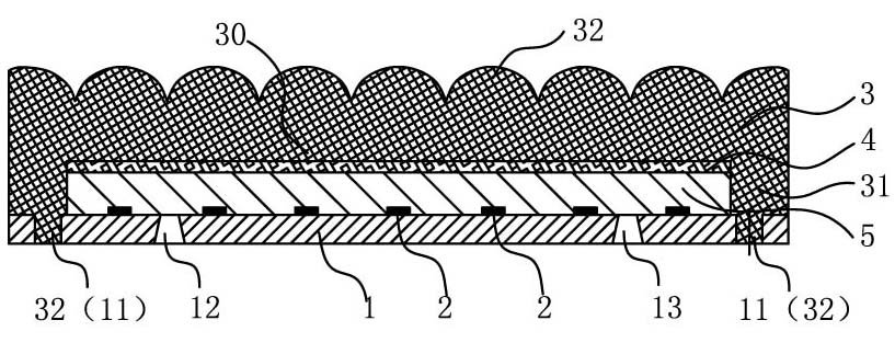
[0024] Depend on figure 1 and figure 2 It can be seen that an LED light source module provided in this specific embodiment includes: a substrate 1 , an LED light-emitting chip 2 , a lens module 3 , a phosphor layer 4 , and a filling body 5 . In this embodiment, the substrate 1 is a rectangular thin plate. There are multiple LED light-emitting chips 2 arrayed on one side surface (upper surface) of the substrate 1 . The lens module 3 includes a main body 30 , a frame 31 , and several lens units 32 . The main body 30 is rectangular, and its edges extend to one side (lower side) to form the rectangular frame 31 . The substrate 1 is covered on the outer side (opening side) of the frame 31 , and forms a closed rectangular box with the lens module 3 ; the LED light-emitting chip 2 is located in the rectangular box. One side (upper surface) of the main body of the lens module 3 has multiple protrusions, and each protrusion is actually a lens unit 32 , and the position of the lens...


PUM


Abstract

The invention discloses an LED light source module which comprises a substrate, a fluorescent powder layer, a lens module and an LED light emitting chip arranged on the substrate. The lens module comprises a main body, a frame and a lens unit, wherein, the edge of the main body stretches towards one side to form the frame, and the main body partially protrudes to form the lens unit; the substrate is covered at the outer side of the frame to form an enclosed box body with the lens module; the LED light emitting chip is arranged in the box body; and the fluorescent powder layer is arranged on the inner surface of the main body. By adopting the LED light source module of the technical scheme of the invention, the substrate and the lens module form the enclosed box body and the fluorescent powder layer is coated on the inner surface of the lens module so that the fluorescent powder layer is far away from the LED light emitting chip, thus being beneficial to lowering the temperature of the fluorescent powder layer, improving the excitation efficiency and the service life of fluorescent powder in the fluorescent powder layer, and increasing the light extraction ratio; and meanwhile by adopting an inwards concave hollow structure of the lens module, the fluorescent powder can be directly dripped on the inner surface of the lens module to form the fluorescent powder layer, so a complicated powder dispersing process is not required, thus achieving simple operation.

Description

technical field [0001] The invention relates to the technical field of LED lighting, in particular to an LED light source module. Background technique [0002] With the advent of blue LEDs, LEDs can be mixed with white light, which can be used as a lighting source. In recent years, LED lighting technology has developed very rapidly, and various LED light source modules have also emerged continuously, and in the latest technology, phosphor layers are generally used to stimulate yellow light. However, the structure of the existing LED light source module is generally more complicated, and its phosphor layer is generally exposed in the air, so the attenuation of the phosphor is faster, the life of the LED light-emitting module is shorter, and the light extraction efficiency is lower; Although the phosphor powder of a few existing LED light source modules is not exposed to the air, it is usually very close to the LED light-emitting chip, causing the temperature of the phosph...

Claims


Application Information

Patent Timeline
Patent Type & Authority Applications(China)
IPC IPC(8): F21S2/00F21V5/04F21V19/00F21V7/22
Inventor 王钢罗滔高艳春薛志强
Owner 中山大学佛山研究院
Learn More