Universal fully-effective generating power machine

A power machine, all-purpose technology, applied in the direction of engine, wind power generation, engine components, etc., can solve problems such as difficulty in meeting grid connection requirements, low conversion rate, loss of water energy, wind energy and steam energy, etc.

Inactive Publication Date: 2010-10-27
黄国宏
View PDF2 Cites 6 Cited by
  • Summary
  • Abstract
  • Description
  • Claims
  • Application Information

AI Technical Summary

Problems solved by technology

Although wind power has developed rapidly at present, so far the world's wind power technology is still unable to fully meet the conditions of rapid and large wind speed and long-term continuous full-angle changes in wind direction.
And when there is no wind, the generator will drive the wind wheel to become a large fan and consume high-power electric energy of the grid, so frequent off-grid and grid-connection are required
Moreover, the output power of the generator will fluctuate sharply due to the instantaneous fluctuation of wind speed, so it is difficult to meet the grid-connected requirements of the grid
In addition, it has many components, complex structure, and high cost, and each wind rotor must be equipped with all equipment and then erected on the top of the tower
[0009] Due to the low conversion rate of various existing water turbines and steam turbines and the serious shortage of existing wind power generating units, not only serious losses have been caused to the developed and utilized water energy, wind energy and steam energy, but also a large number of clean, pollution-free and cheap And the renewable and disappearing water energy, wind energy and ubiquitous solar energy resources will be lost for a long time because they cannot be effectively developed, and cannot benefit mankind

Method used


Image

  • Universal fully-effective generating power machine
  • Universal fully-effective generating power machine
  • Universal fully-effective generating power machine

Examples


Embodiment Construction

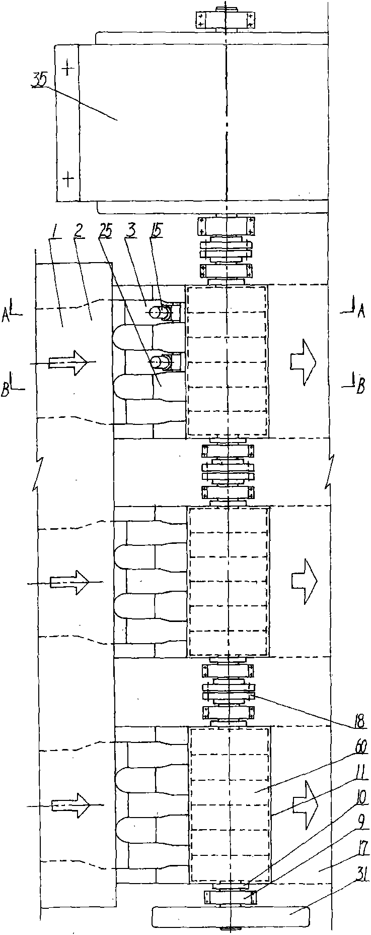
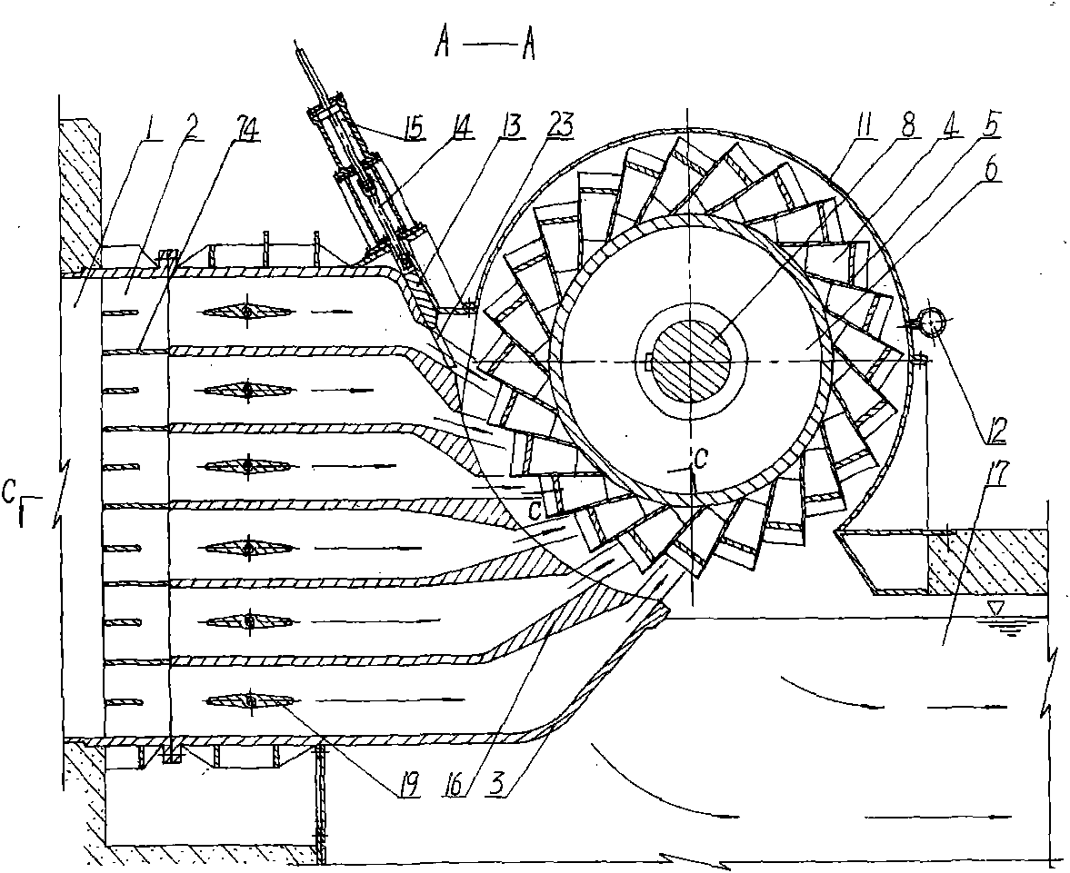
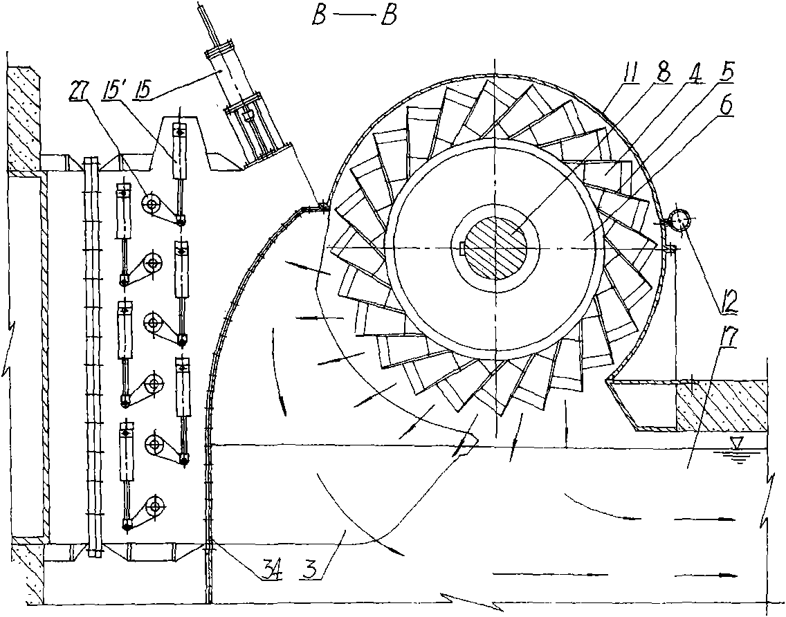
[0038] Figure 1 to Figure 9 A first embodiment of the invention is shown. This embodiment is an all-purpose full-effect water motor that converts water energy into rotational mechanical energy, and is a large-scale hydrodynamic generator set that drives a generator jointly after the main shafts of three all-purpose full-effect water motors are connected in sequence.

[0039] As shown in the figure: the water outlet ends of each pressure water delivery channel 1 are respectively connected with a drainage chamber 2, and the water outlet ends of the drainage chamber 2 are fixedly connected with three jet ports 3 with a certain distance from each other and a rectangular cross-sectional shape. . The inside of the jet port 3 is respectively provided with five deflectors 16 with different angles, and there is a certain distance between the two exit edges of the exit end of the deflector 16, so that the jet port 3 is divided into six rectangular exit ports 21 and other Correspondin...


PUM


Abstract

The invention relates to a universal fully-effective generating power machine belonging to generating power equipment which can fully and effectively convert conventional energy resources such as water energy, steam energy and the like and new energy resources such as wind energy, steam energy formed by solar heating, tidal water energy and the like into rotating mechanical energy. The machine mainly comprises one or a plurality of jet orifices, a regulating mechanism of the jet orifices, one or a plurality of universal fully-effective rotating wheels, a speed regulator and the like, wherein, the universal fully-effective rotating wheels correspond to the jet orifices and are arranged on a main shaft. The machine can fully develop and utilize water energy, steam energy and wind energy of all types, can fully and effectively convert the utilized water energy, steam energy and wind energy into rotating mechanical energy, can fully replace all current water turbines, steam turbines and wind turbines, and has the advantages of simple structure, reliable performance, low manufacturing cost and easy implementation. Thus, the universal fully-effective generating power machine can replace equipment of hydraulic, thermal and wind power generation industries, and can promote rapid development of new energy resource generating industries such as hydraulic fully-effective power generation, hydraulic wind power generation, solar steam power generation and the like to become main energy source power generating modes.

Description

Technical field [0001] The invention belongs to the all-round effective conversion of conventional energy such as water energy, steam energy formed by overheating of coal, oil, natural gas and nuclear energy, and new energy such as wind energy, steam energy formed by solar heating, and tidal water energy, into rotating mechanical energy. power generation equipment. According to its different driving force and working medium, it can be divided into all-round full-effect water motor, all-round full-effect steam motor and all-round full-effect wind-hydraulic motor. Background technique [0002] At present, the power equipment of hydroelectric power generation is divided into two types: impact turbine and impulse turbine. [0003] In counterattack type, mixed flow, axial flow and tubular water turbines, the runner, the periphery of the runner or its upstream is composed of several blades with wing-shaped cross-sections arranged between the upper crown and the lower ring or on t...

Claims


Application Information

Patent Timeline
IPC IPC(8): F03B1/00F03B1/04F03B13/12F01K7/00F03D5/00F03G6/00
CPCY02E10/46Y02E10/223Y02E10/70Y02E10/20Y02P70/50
Inventor 黄国宏
Owner 黄国宏
Why Eureka
Try Eureka