
Flyback converter leakage inductance energy absorption feedback circuit of photovoltaic grid-connected inverter

A leakage inductance energy absorption, flyback converter technology, applied in photovoltaic power generation, electrical variable adjustment, output power conversion devices, etc. Eliminates voltage spikes and improves efficiency

Inactive Publication Date: 2012-08-22
盈威力新能源科技(上海)有限公司
View PDF5 Cites 0 Cited by
  • Summary
  • Abstract
  • Description
  • Claims
  • Application Information

AI Technical Summary

Problems solved by technology

Among them, the lossy RCD snubber circuit has a simple structure, low cost, and is easy to implement, but all the energy in the leakage inductance is consumed in the snubber resistor, which reduces the efficiency of the flyback converter. Low-frequency occasions; non-destructive LCD absorption circuit has high efficiency, which is more complicated than lossy RCD absorption circuit, and is not suitable for high-frequency occasions; active clamping circuit can eliminate voltage spikes, improve system efficiency, and can realize soft switching; passive clamping circuit The bit circuit does not add active switches, and can also eliminate voltage spikes and improve efficiency, but the closed-loop design is more complicated and loses the original isolation performance of the transformer

Method used


Image

  • Flyback converter leakage inductance energy absorption feedback circuit of photovoltaic grid-connected inverter
  • Flyback converter leakage inductance energy absorption feedback circuit of photovoltaic grid-connected inverter
  • Flyback converter leakage inductance energy absorption feedback circuit of photovoltaic grid-connected inverter

Examples


Embodiment

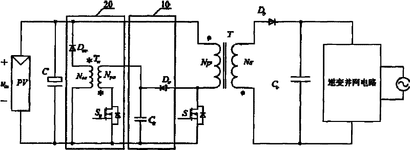
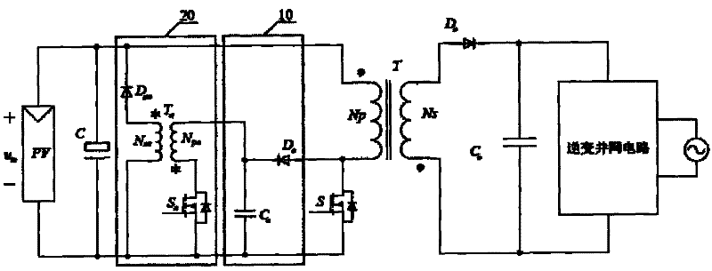
[0028] Such as figure 1 As shown, it is a circuit schematic diagram of a photovoltaic grid-connected inverter circuit using the leakage inductance energy absorption feedback circuit of the flyback converter. Its structure includes a primary circuit, a high-frequency transformer T and a secondary circuit. Among them: the primary circuit It consists of a photovoltaic battery pack PV, an input capacitor C, the leakage inductance energy absorption feedback circuit of the flyback converter of the present invention and a main power switch tube S; the high-frequency isolation transformer T is composed of a primary winding N p and the secondary winding N s Composed; the secondary circuit consists of a rectifier diode D o , output filter capacitor C o and inverter grid-connected circuit.

[0029] The leakage inductance energy absorption and feedback circuit of the flyback converter of the present invention includes an absorption circuit 10 and a feedback circuit 20, and the input vo...


PUM


Abstract

The invention relates to a flyback converter leakage inductance energy absorption feedback circuit of a photovoltaic grid-connected inverter, which comprises an absorption circuit and a feedback circuit; the input voltage of the photovoltaic grid-connected inverter is sequentially and electrically connected with the feedback circuit and the absorption circuit; the output end of the absorption circuit is connected with the primary winding of a high-frequency isolation transformer of the photovoltaic grid-connected inverter by a main power switch; the secondary winding of the high-frequency isolation transformer of the photovoltaic grid-connected inverter is connected with a inverting grid-connected circuit; the absorption circuit absorbs the leakage inductance energy of the high-frequency isolation transformer in the main circuit of the photovoltaic grid-connected inverter and the leakage inductance energy is fed back to the input end of the photovoltaic grid-connected inverter by the feedback circuit; simultaneously, the voltage of a clamping capacitance is regulated so that the voltage of the clamping capacitance follows the input voltage of the photovoltaic grid-connected inverter and the sum of the network voltage and the reflected voltage of the inverting grid-connected inverter so as to guarantee that the main inductance energy of the photovoltaic grid-connected inverter is not absorbed, simultaneously, restrains the voltage peak of the switch pipe of the main power and improves the efficiency of the flyback converter.

Description

technical field [0001] The invention relates to a leakage inductance energy absorption feedback circuit, in particular to a new solar energy technology field, which is applied to a leakage inductance energy absorption feedback circuit of a flyback converter of a photovoltaic grid-connected inverter. Background technique [0002] As an inexhaustible new energy source, solar energy has very broad application and development prospects. Using solar power as an important way to solve environmental and energy crises is gaining huge economic and social benefits. [0003] Photovoltaic grid-connected inverters are an important tool for generating electricity using solar energy. With the continuous development of new energy technologies, the reliability, efficiency and power density of photovoltaic grid-connected inverters, especially micro-photovoltaic grid-connected inverters, are of great importance. higher and higher requirements. Various countries, including the United States, E...

Claims


Application Information

Patent Timeline
Patent Type & Authority Patents(China)
IPC IPC(8): H02J3/38H02M3/28H02M3/335
CPCY02E10/563Y02E10/56
Inventor 古俊银张君君
Owner 盈威力新能源科技(上海)有限公司
Learn More