
Central heating system and method for coupling circulating water heat pump of power plant with cogeneration

A technology for co-generation of heat and power and circulating water, applied in the energy field, can solve the problems of affecting the quality of life, low energy efficiency of heat pumps, poor heating effect, etc., and achieve the effect of regional central heating

Active Publication Date: 2014-12-03
NORTH CHINA ELECTRIC POWER UNIV (BAODING)
View PDF4 Cites 0 Cited by
  • Summary
  • Abstract
  • Description
  • Claims
  • Application Information

AI Technical Summary

Problems solved by technology

However, most of these heat pumps have low energy efficiency in low temperature climates, that is to say, their heating effect is poor at the coldest time of the year, which greatly affects the quality of life

Method used


Image

  • Central heating system and method for coupling circulating water heat pump of power plant with cogeneration
  • Central heating system and method for coupling circulating water heat pump of power plant with cogeneration

Examples


Embodiment 1

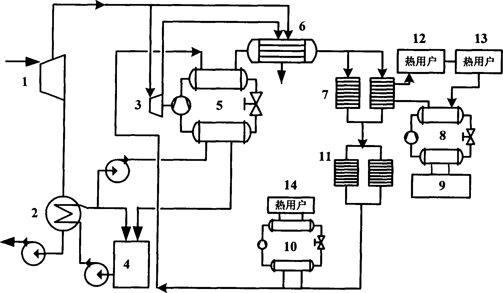
[0018] The steam enters the steam turbine 1 of the power plant to do work, and the exhaust steam from the steam turbine 1 of the power plant enters the condenser 2 to be condensed and sent to the boiler feed water. The circulating cooling water of the condenser is extracted from the circulating water cooling facility 4 of the power plant, and the circulating water enters the condenser 2 to participate in heat exchange, and the temperature rises. Part of the high-temperature circulating water goes to the circulating water cooling facility 4 of the power plant for cooling, and the other part is used as the first type The low-temperature heat source of the heat pump system, after being absorbed by the heat pump system 5 of the first type, its temperature is lowered, and the water after lowering the temperature also flows into the circulating water cooling facility 4 of the power plant. Part of the steam that has done work in the steam turbine 1 is extracted, and a part of it is se...

Embodiment 2

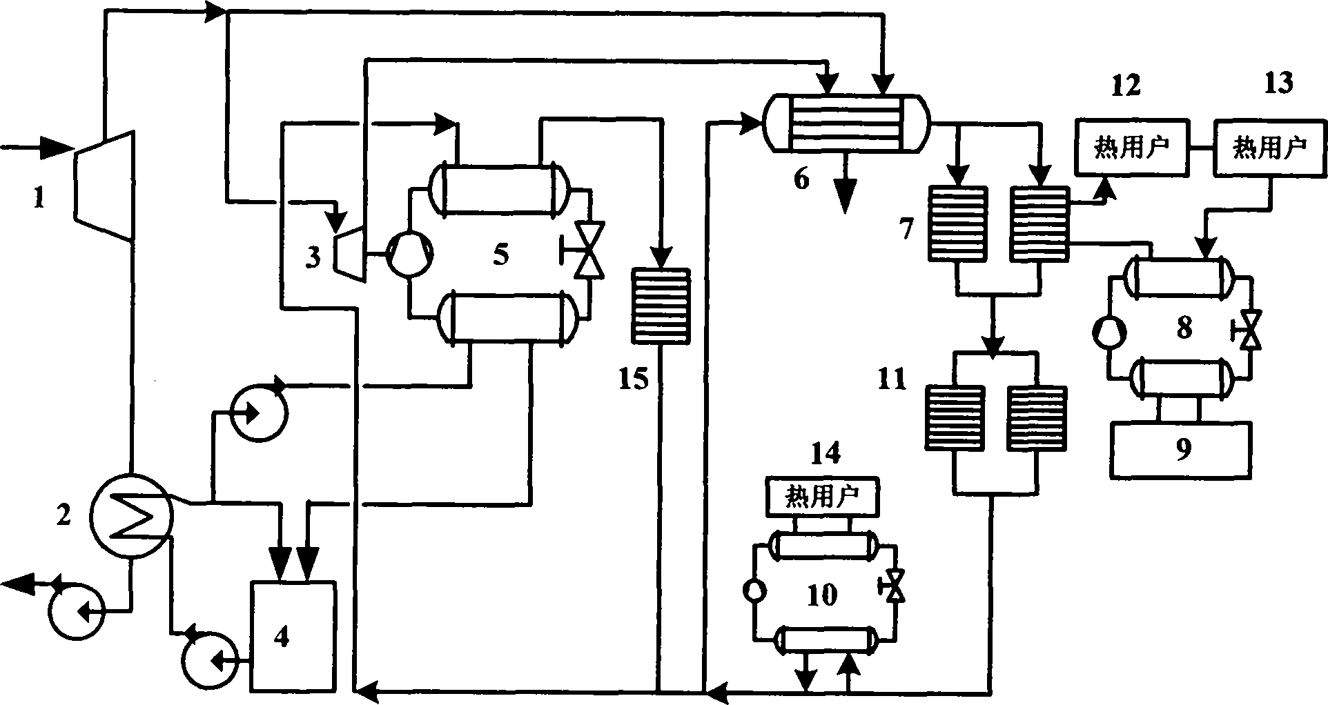
[0021] Embodiment 2 is similar to Embodiment 1, the difference is that the first type of heat pump in Embodiment 1 heats the heat network water and then is heated by the heat network heater, and then sent to the secondary heat network heater 7 to provide heating for users, while in Embodiment 1 The first type of heat pump in 2 realizes close-distance heating for the area near the power plant.

[0022] In Example 2, after the heating network water of the primary heating network returns to the power plant, part of it enters the first type heat pump system 5 for heating, and part of it enters the primary heating network heater 6 for heating. The heating network water heated by the first type heat pump system 5 is transported to the area near the power plant to realize short-distance heating, while the heating network water heated by the primary heating network heater 6 realizes long-distance heating.


PUM


Abstract

The invention belongs to heating systems and methods for coupling a circulating water heat pump of a power plant with cogeneration in the field of energy sources. The system consists of a steam turbine, a steam compressed heat pump, a small backpressure steam turbine, a heating network heater and corresponding pipelines and accessory equipment. The system uses circulating water of the power plant as a heat source of a heat pump; a heat pump compressor is driven by an intermediate-pressure steam driving small steam turbine which does work in the power plant; and the small team turbine exhausts steam which enters the heating network heater to heat the heating network water. In addition, the function for extracting the heat from a low-temperature heat source except the circulating water of the power plant can be achieved by using the coupling of an absorbing type heat pump with a primary network and a secondary network in the heating network. The invention fully utilizes a large amount of cold source loss of a condensing type unit, overcomes the defects of the cogeneration and the heat pump by using the synergistic action of the circulating water heat pump of the power plant with the cogeneration and realizes the regional centralized heating. By using the technical measures, the thermal economy of the central heating system taking a team turbine unit power plant as the center is improved.

Description

technical field [0001] The invention belongs to the field of energy, and particularly relates to a centralized heating system and method for power plant circulating water heat pump coupled heat and power cogeneration. The system expands the heat supply capacity of the power plant and improves the thermal power Thermal economy of power plants. technical background [0002] Realizing regional centralized heating through cogeneration of thermal power plants can realize energy cascade utilization, which is one of the efficient and environmentally friendly energy utilization methods. At present, when building new power plants in my country, cogeneration thermal power plants are given priority in places with regional heat loads. [0003] In cogeneration technology, the steam turbine can use extraction condensing and back pressure units. Among them, the cold source loss of the back pressure unit is used for heating. The thermal efficiency of the whole plant is almost equal to the ...

Claims


Application Information

Patent Timeline
Patent Type & Authority Patents(China)
IPC IPC(8): F24D3/18F01K17/02
CPCY02B30/16Y02E20/14Y02B30/12Y02B30/00Y02P80/15
Inventor 张永生于刚卞双邢长燕张光鞠翠玲
Owner NORTH CHINA ELECTRIC POWER UNIV (BAODING)
Learn More