Novel oxy-fuel combustion glass melting furnace

An all-oxygen combustion, glass melting furnace technology, applied in glass production, glass furnace equipment, glass manufacturing equipment and other directions, can solve the problems of increasing output, unable to increase the temperature of the melting furnace indefinitely, to increase output, be conducive to clarification and uniformity Optimal, easy-to-achieve effects

Active Publication Date: 2010-09-22
株洲旗滨集团股份有限公司 +1
View PDF9 Cites 8 Cited by
  • Summary
  • Abstract
  • Description
  • Claims
  • Application Information

AI Technical Summary

Problems solved by technology

However, for flame-fired furnaces, even oxy-fuel glass furnaces, on the one hand, are limited by the combustion volume of the burner, and on the other hand, by the refractory materials of the furnace, that is, the temperature of the furnace cannot be increased indefinitely to increase production

Method used


Image

  • Novel oxy-fuel combustion glass melting furnace
  • Novel oxy-fuel combustion glass melting furnace
  • Novel oxy-fuel combustion glass melting furnace

Examples


Embodiment 1

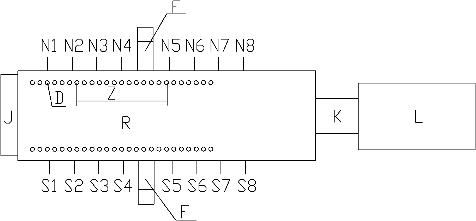
[0023] Example 1, please refer to image 3 , Figure 4 As shown, a novel oxy-fuel combustion glass melting furnace of the present invention includes a feeding port J, a melting part R, a neck or a flow hole K and a cooling part L; a feeding port J, a melting part R, a neck Or the liquid flow hole K and the cooling part L are connected in sequence; the melting part R includes a melting pool and parapets X arranged on both sides of the melting pool; the melting part R is provided with a hot spot along the middle section of the feeding direction of the molten glass ; There is also a flue F and 8 oxygen burners on the parapet walls on both sides of the melting part R, of which one side is the oxygen burner S1, the oxygen burner S2, the oxygen burner S3, the oxygen burner Burning gun S4, full oxygen burning gun S5, full oxygen burning gun S6, full oxygen burning gun S7, full oxygen burning gun S8; the other side is full oxygen burning gun N1, full oxygen burning gun N2, full oxyge...

Embodiment 2

[0032] Embodiment 2, a new type of all-oxygen glass melting furnace of the present invention, please refer to Figure 5 As shown, the difference from Example 1 is that the arrangement of the pill-shaped molybdenum electrodes D' in the third area near the neck or the liquid hole K side is along the direction perpendicular to the flow of the molten glass. Give directions in two rows. Apparently, the arrangement of the pill-shaped molybdenum electrodes D' in the third area on the side of the neck or the flow hole K is beneficial to the pill-shaped molybdenum electrodes D' when the temperature of the molten glass rises and the convection strengthens, which is equivalent to that in the molten glass. The horizontal direction of the kiln acts as a barrier, which can improve the horizontal and vertical convection of the molten glass, prolong the residence time of the molten glass in the melting furnace, and reduce the amount of molten glass flowing back from the cooling part L to the ...


PUM


Abstract

The invention discloses a novel oxy-fuel combustion glass melting furnace, which comprises a feed opening part, a melting part, a neck or throat part and a cooling part, wherein the feed opening, the melting part, the neck or throat part and the cooling part are connected with one another in succession; the melting part comprises a melting tank and breast walls arranged on two sides of the melting tank; the melting part is provided with a hot spot along the middle section of the feeding direction of glass liquid; the breast wall on each side of the melting part is at least provided with a flue and an oxy-fuel combustion gun, and the flues on the breast walls on the two sides of the melting part are opposite to each other, and the oxy-fuel combustion guns on the two sides are arranged in astaggered mode; and tank bottom of the melting tank of the melting part is provided with a plurality of pellet-shaped molybdenum electrodes. The novel oxy-fuel combustion glass melting furnace has the characteristics of having a simple structure, being easy to implement, being favorable for improving the heat efficiency of the glass melting furnace, reducing the discharge of NOx pollutants and the greenhouse gas CO2, improving the glass quality, saving the investment cost of the melting furnace, prolong the service life of the melting furnace and the like.

Description

technical field [0001] The invention relates to the technical field of glass melting furnaces, in particular to a novel oxy-fuel combustion glass melting furnace. Background technique [0002] Generally, most glass melting furnaces use flame combustion, and the common ones are regenerator horseshoe flame glass melting furnace and regenerator cross-flame glass melting furnace. The combustion medium of these melting furnaces mostly uses air to support combustion. However, when using air as a combustion aid, only 20% of the oxygen in the air really participates in combustion, while the remaining 80% of nitrogen and other gases do not participate in combustion, and will be released as NO after consuming a large amount of heat. x Pollutants are discharged into the atmosphere, making these furnaces not only prone to serious pollution of the atmosphere, but also reducing the thermal efficiency of the furnace. See figure 1 As shown, since the regenerator horseshoe flame glass melt...

Claims


Application Information

Patent Timeline
IPC IPC(8): C03B5/00
CPCY02P40/50
Inventor 俞其兵邵景楚施敖荣官立民黄勇郭建峰
Owner 株洲旗滨集团股份有限公司
Why Eureka
Try Eureka