
System for recycling SO2 and NO from oxygen-enriched combustion boiler fume CO2 collection

A boiler flue gas, oxygen-enriched combustion technology, applied in the direction of climate sustainability, air quality improvement, direct carbon dioxide emission reduction, etc. Power consumption and dehydration power consumption, eliminating desulfurization and denitrification devices, and improving combustion and heat transfer efficiency

Inactive Publication Date: 2010-09-22
NORTH CHINA ELECTRIC POWER UNIV (BAODING)
View PDF5 Cites 24 Cited by
  • Summary
  • Abstract
  • Description
  • Claims
  • Application Information

AI Technical Summary

Problems solved by technology

However, the existing SO2 treatment method mainly adopts flue gas desulfurization technology, the process is complicated, the device is huge, and a large amount of absorbent is consumed. The desulfurization products are basically solid waste that cannot be fully utilized, and it is difficult to recycle Utilization will cause secondary pollution; if SO2 and CO2 are liquefied, compressed and stored together, it will not only increase the compression power consumption, but also increase the CO2 Detrimental effects of sequestration
The mainstream industrial application of removing NOX from flue gas is Selective Catalytic Reduction (SCR), which uses expensive catalysts and amino absorbents to convert NOX into milliliters Useless N2; or use low NOX combustion technology, but the reduction of NO is limited, and at the expense of part of the combustion efficiency
At present, there is no technology with simple process, low investment, low operating cost, simultaneous desulfurization and nitrogen oxide removal, and high efficiency

Method used


Image

  • System for recycling SO2 and NO from oxygen-enriched combustion boiler fume CO2 collection
  • System for recycling SO2 and NO from oxygen-enriched combustion boiler fume CO2 collection

Examples


Embodiment Construction

[0030] The invention provides a CO 2 Recovery of SO from capture 2 With NO system, the present invention will be further described below in conjunction with the accompanying drawings and specific embodiments.

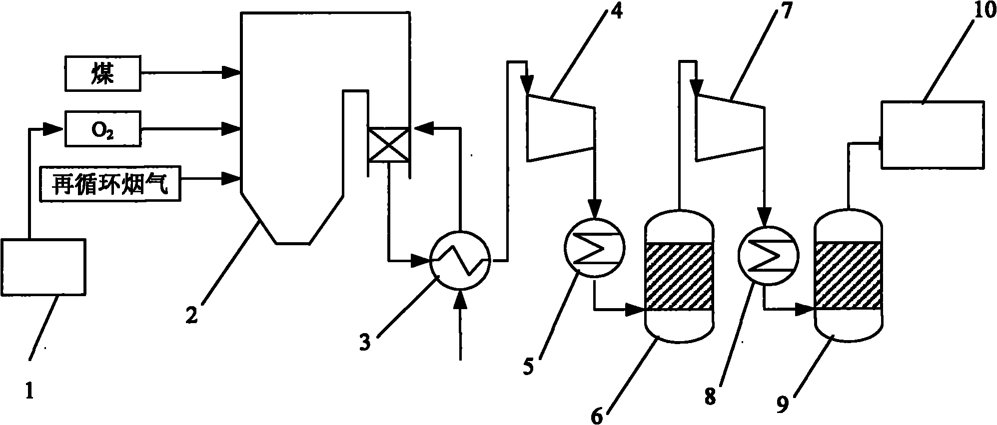
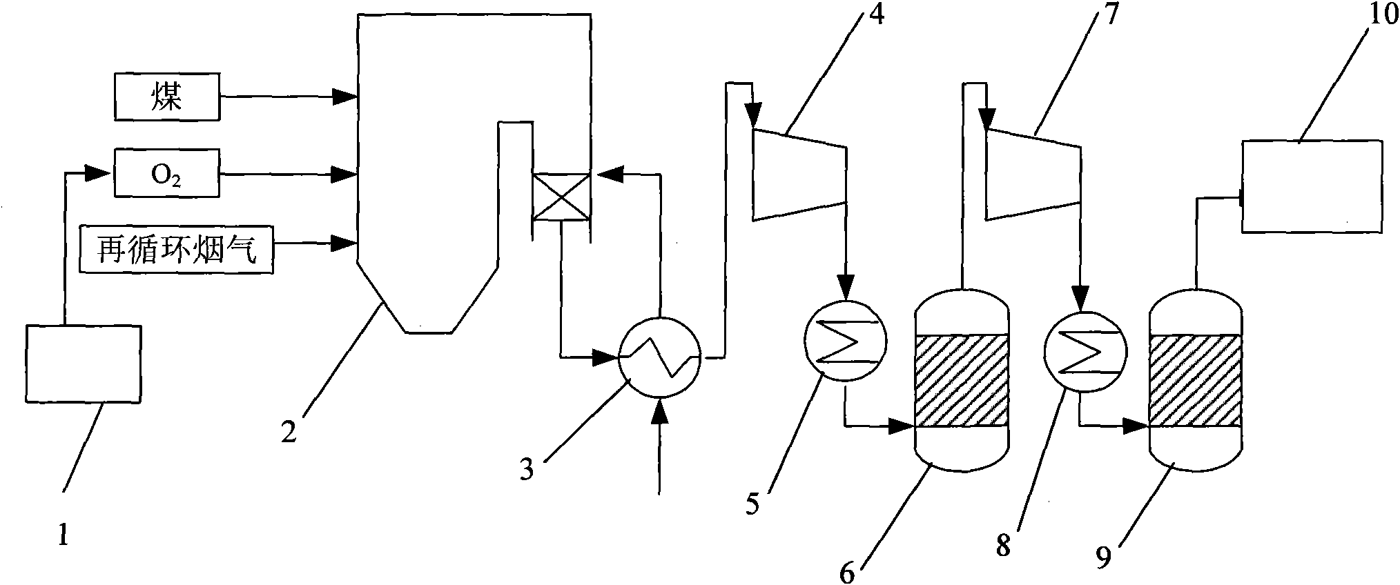
[0031] Such as figure 1 As shown, the exhaust port of the boiler 2 is connected to the first cooler 3, and then connected with the primary compressor 4, the second cooler 5, the first contact tower 6, the secondary compressor 7, the third cooler 8, The second contact tower 9 and the carbon dioxide compression and condensation device 10 are connected in sequence.

[0032] The working process of the system is: after the oxygen produced in the air separation device 1 is mixed with the recirculated flue gas in a certain proportion, they are sent to the furnace of the boiler 2 together with pulverized coal for combustion, and the burned boiler exhaust smoke passes through the first cooler 3 Cool to 30°C and send it to the primary compressor 4 Pressurize to 1.5-2MPa. The ...


PUM


Abstract

The invention relates to a system for recycling SO2 and NO from oxygen-enriched combustion boiler fume CO2 collection and belongs to boiler fume processing equipment. A method for recycling the SO2 and NO from the oxygen-enriched combustion boiler fume CO2 collection comprises the following steps of: heating boiler feed water by using the fume discharged by a boiler first; cooling the fume to the temperature of 30 DEG C and pressurizing the fume; reacting the SO2, the NO, O2 and H2O in the pressurized fume in a first contact tower, wherein the SO2 is totally oxidized to generate SO3 and dilute sulfuric acid; and continuously pressurizing the reacted fume to finish the recycling of the SO2 and the NO, wherein the NO is oxidized to NO2 in a second contact tower and is reacted with the water to generate dilute nitric acid. In the system, no catalyst is needed, the removal rate of sulfur oxides approaches 100 percent, and the removal rate of nitrogen oxides is over 90 percent. The system has the advantages of reducing content of residual oxygen and water, improving CO2 purity, reducing CO2 compression power consumption and dehydration power consumption, saving devices for low NOX combustion, desulfurization and denitration, and improving energy utilization efficiency by heating the boiler feed water with the heat of cooled fume, the heat generated by compression and the reaction heat in the contact tower.

Description

technical field [0001] The invention belongs to boiler flue gas treatment equipment, in particular to a CO 2 Recovery of SO from capture 2 system with NO. Background technique [0002] Environmental problems such as greenhouse effect and acid rain caused by the use of fossil energy such as coal, oil and natural gas have become a restrictive factor for social and economic development. Coal-fired power stations are CO 2 Concentrated emission sources and generation of SO 2 , NO X largest source of pollution, therefore, CO 2 Capture and storage and SO 2 , NO X The technology of integrated removal and integration has become the development trend of clean coal power generation technology in the future. [0003] The main advantage of oxyfuel combustion technology is the direct capture of CO 2 Compress it to liquefy and store it. SO in boiler flue gas 2 , NO X The removal or utilization of resources is a focus of much attention. But existing SO 2 The treatment method ma...

Claims


Application Information

Patent Timeline
IPC IPC(8): B01D53/76B01D53/62B01D53/60C01B31/20C01B21/40C01B17/74F23J15/06F23J15/02C01B32/50
CPCY02A50/20Y02E20/32Y02E20/34Y02P20/10
Inventor 阎维平鲁晓宇高正阳王春波董静兰
Owner NORTH CHINA ELECTRIC POWER UNIV (BAODING)
Learn More