
Cooling device of flame detector

A technology of flame detectors and cooling devices, which is applied to the cooling of instruments, parts of instruments, instruments, etc., and can solve the problems of not being able to see light, inconvenient operation, and difficult installation

Inactive Publication Date: 2010-09-15
SUZHOU BAOLIAN HEAVY IND
View PDF5 Cites 2 Cited by
  • Summary
  • Abstract
  • Description
  • Claims
  • Application Information

AI Technical Summary

Problems solved by technology

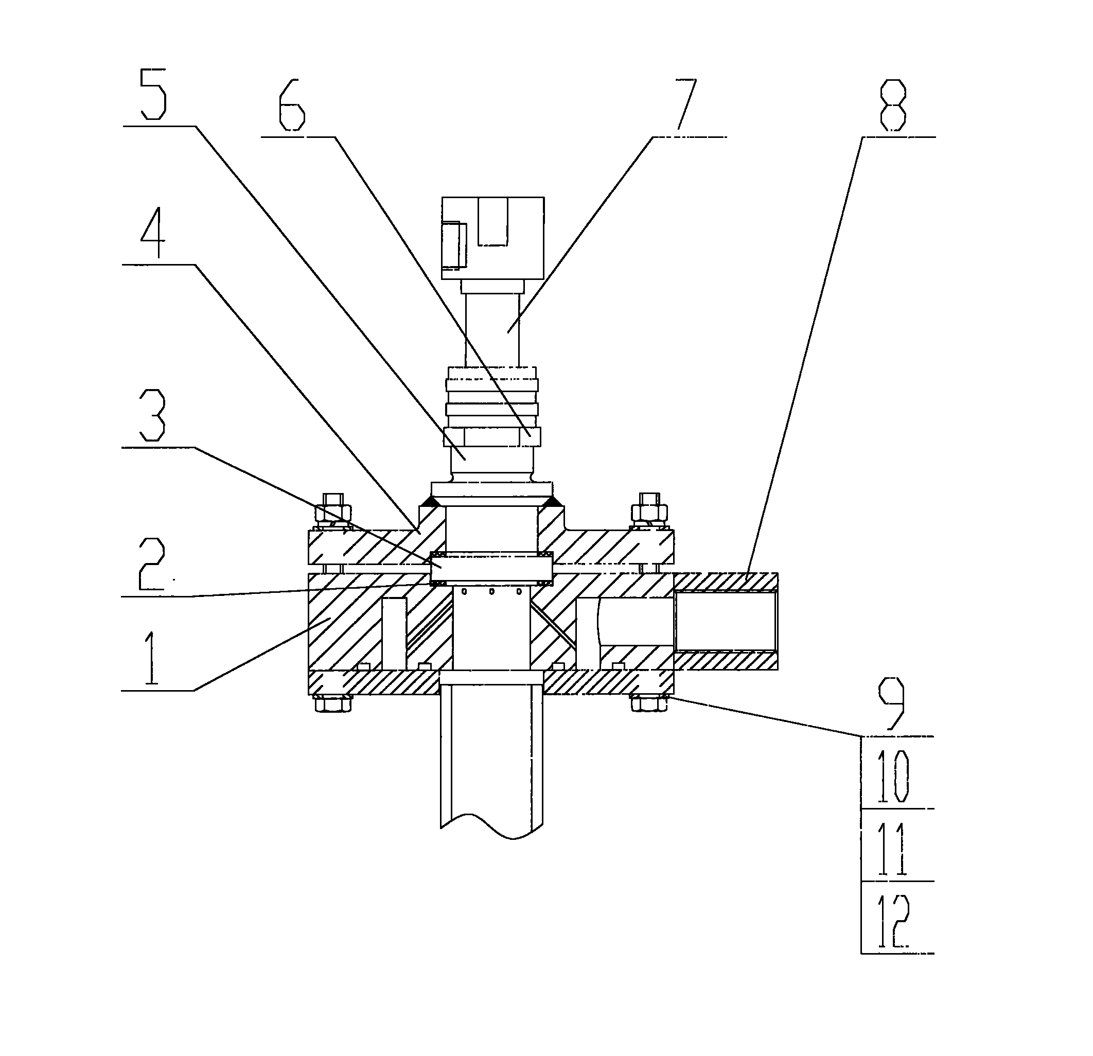
[0002] At present, flame detectors are commonly used in the metallurgical industry. In order to protect the flame detectors from being burned, there is an existing cooling device for protecting the flame detectors from being burned, including cooling plates, nuts, and joints; the cooling device is arranged on The tail of the top lance is cooled with cooling nitrogen gas during steelmaking to prevent the filter glass from being burned at high temperature; the cooling device (see Figure 1) is blown upwards due to the cooling nitrogen gas, causing the high temperature gas to directly act on the The filter glass plate, the glass plate is blurred, and the light cannot be seen when the flame is detected. The glass plate must be removed and wiped clean or replaced. When removing, 4 bolts must be unscrewed. Since the cooling device is installed at a higher position, It is very inconvenient to operate and more difficult to install; and the demolition work cannot be operated during steelmaking, which causes the system to self-lock due to poor flame signal acquisition, which brings a lot of trouble and unnecessary losses to production

Method used


Image

  • Cooling device of flame detector
  • Cooling device of flame detector
  • Cooling device of flame detector

Examples


Embodiment Construction

[0014] A cooling device for a flame detector of the prior art shown in accompanying drawing 1 includes a cooling plate 1, a pressing plate 4, a glass plate 3, and a transition joint 5; the pressing plate 4 presses the glass plate 3 on the cooling plate, and passes through 4 groups Bolts 12, nuts 11, flat washers 9, and spring washers 10 are fixed on the cooling plate 1; a sealing ring 2 is arranged between the glass plate 3 and the pressing plate; one end of the transition joint is welded on the pressing plate 4, and the other end is connected to a flame detector 7; There is a through hole on the cooling plate, and the flame detector 7 can be seen in the through hole through the glass plate 3 . The cooling plate 1 is provided with a joint 8, and the through hole communicates with the joint through an air channel, and the air channel is inclined upward, so that the cooling nitrogen is blown upward, causing the high-temperature gas to directly act on the filter glass plate, and t...


PUM


Abstract

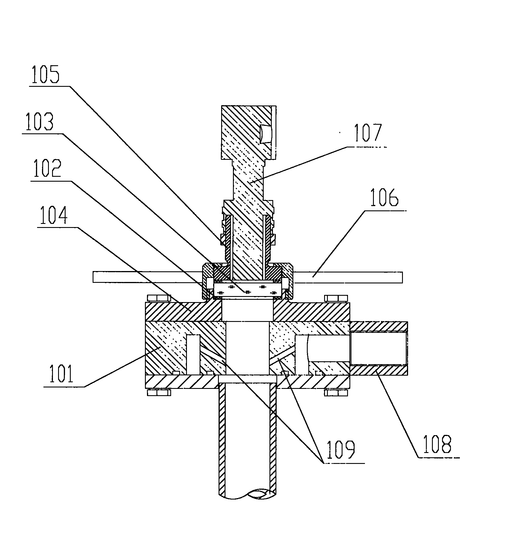
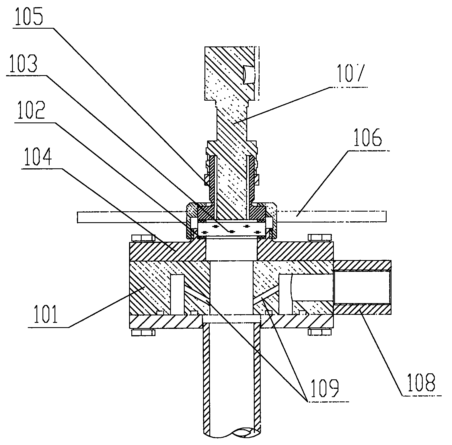
The invention relates to a cooling device of a flame detector, comprising a cooling plate, a pressing plate, a glass plate and a transition joint. The cooling plate is mounted on the pressing plate; the transition joint fixes the glass plate on the pressing plate through screw threads; the other end of the transition joint is connected with the flame detector; the cooling plate and the pressing plate are provided with through holes which are communicated with each other; the inside of the through holes can be seen through the glass plate; a handle is arranged outside the transition joint so that it is convenient to assemble and disassemble the transition joint; the cooling plate is provided with a joint, and the through holes and the joint are communicated through an airway which declines downwards. In the cooling device of the flame detector, the glass plate is fixed on the pressing plate by the transition joint and the screw threads, meanwhile, the transition joint is provided with the handle and can be conveniently assembled and disassembled; and when the glass plate needs to be exchanged or washed, the operation is very convenient. Furthermore, the airway in the cooling plate is arranged to decline downwards, thereby avoiding cooling nitrogen directly rushing at the glass plate to influence the transparency of the glass plate.

Description

technical field [0001] The invention relates to a cooling device, in particular to a cooling device for protecting a flame detector from being burned in the metallurgical industry, and belongs to the technical field of metallurgical equipment. Background technique [0002] At present, flame detectors are commonly used in the metallurgical industry. In order to protect the flame detectors from being burned, there is an existing cooling device for protecting the flame detectors from being burned, including cooling plates, nuts, and joints; the cooling device is arranged on The tail of the top lance is cooled with cooling nitrogen gas during steelmaking to prevent the filter glass from being burned at high temperature; the cooling device (see Figure 1) is blown upwards due to the cooling nitrogen gas, causing the high temperature gas to directly act on the The filter glass plate, the glass plate is blurred, and the light cannot be seen when the flame is detected. The glass plat...

Claims


Application Information

Patent Timeline
Patent Type & Authority Applications(China)
IPC IPC(8): G12B15/04
Inventor 曹卫文吴文超张海雅
Owner SUZHOU BAOLIAN HEAVY IND
Learn More