
Liquid crystal display device and its driving method

A technology of liquid crystal display and driving method, which is applied in the field of liquid crystal display and its driving, and can solve problems such as poor driving, increased line width of black matrix light-shielding film, and reduced aperture ratio

Inactive Publication Date: 2008-09-17
AU OPTRONICS CORP
View PDF4 Cites 0 Cited by
  • Summary
  • Abstract
  • Description
  • Claims
  • Application Information

AI Technical Summary

Problems solved by technology

[0012] However, the former is easily affected by the stability of the manufacturing process, resulting in poor driving due to the coupling of the source line 11 and the auxiliary capacitor 12, while the latter has the inevitable increase in the line width of the black matrix light-shielding plate, which reduces the aperture ratio (Aperture Ratio) lack of

Method used


Image

  • Liquid crystal display device and its driving method
  • Liquid crystal display device and its driving method
  • Liquid crystal display device and its driving method

Examples


Embodiment Construction

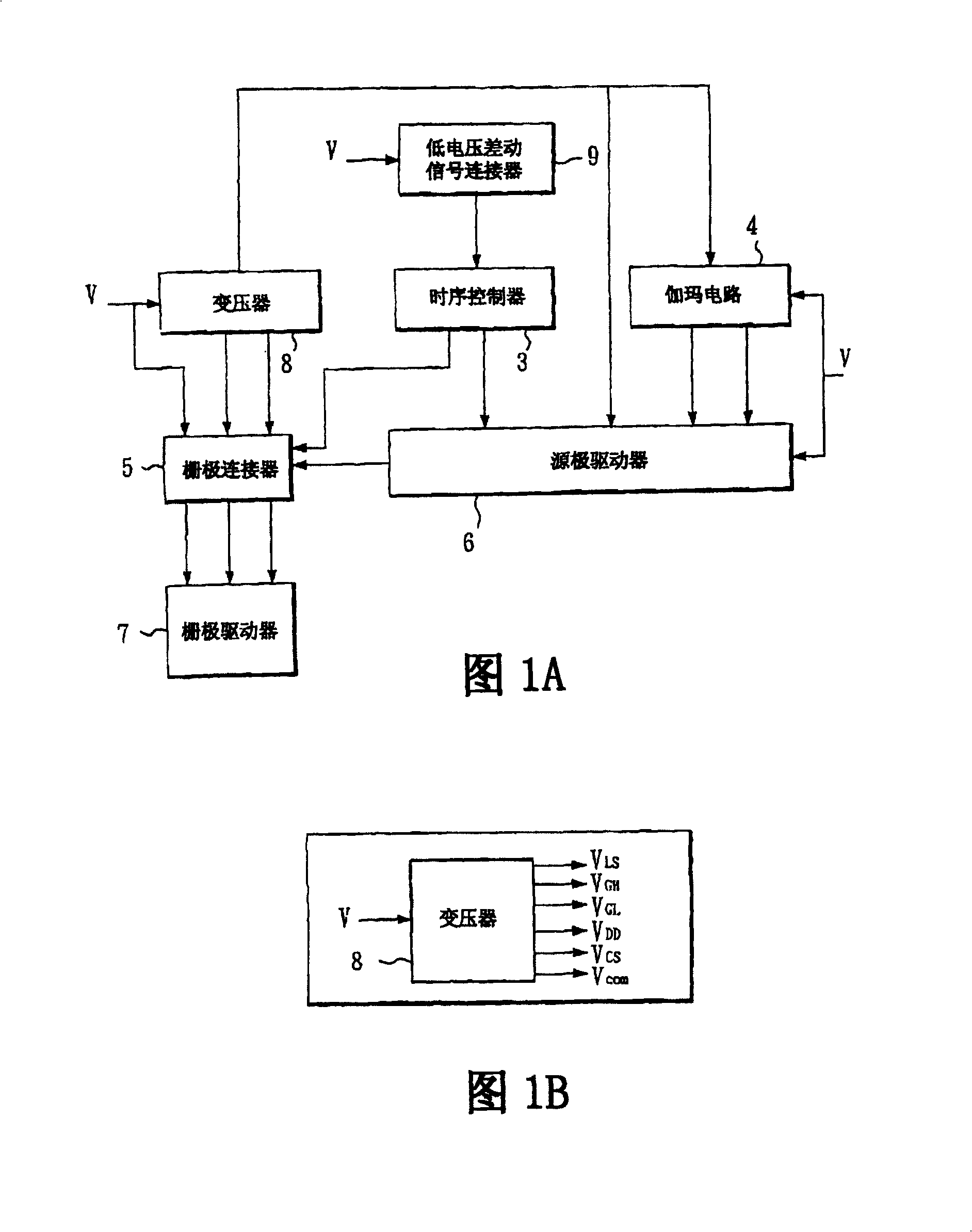
[0048] Please refer to FIG. 1A and FIG. 1B together. FIG. 1A is a block diagram of a liquid crystal display driving system according to a preferred embodiment of the present invention, and FIG. 1B is a schematic diagram showing a transformer of a liquid crystal display driving system according to a preferred embodiment of the present invention.

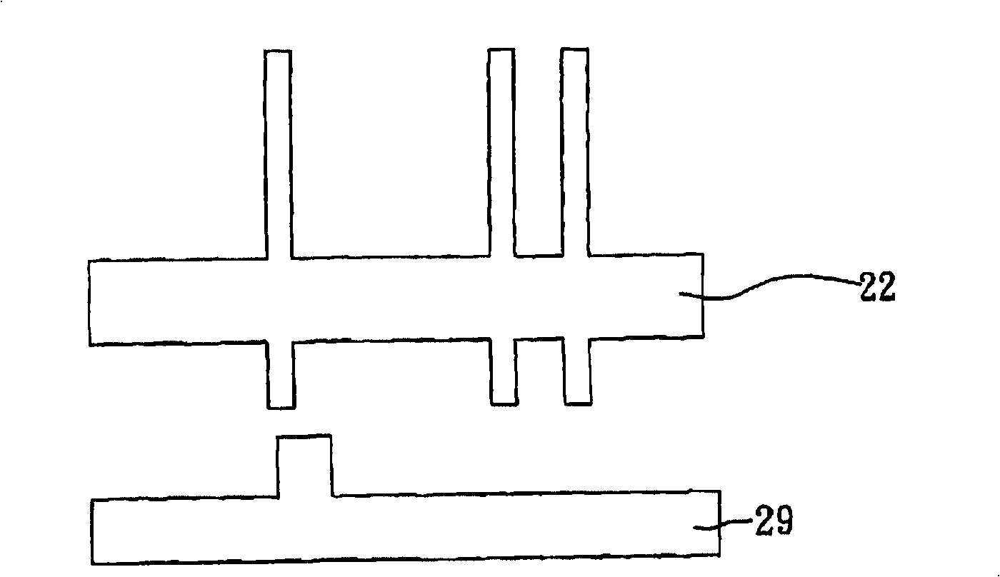
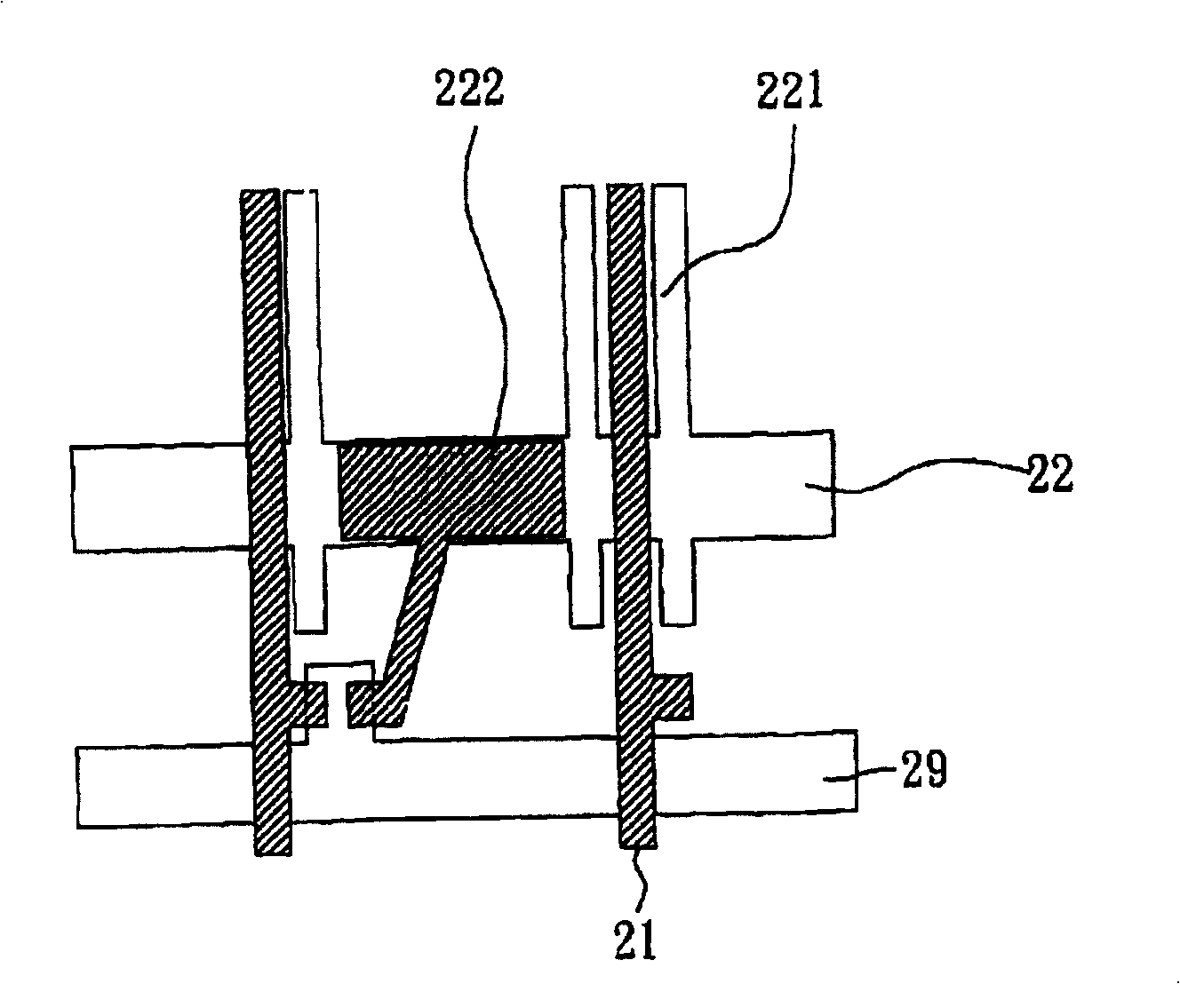
[0049] The liquid crystal display driving system shown in Fig. 1A, Fig. 1B is to electrically connect a plurality of pixel electrodes 24 (such as Figure 2D ), and it includes a low voltage differential signal connector 9, a transformer 8, a timing controller 3, a gamma circuit 4, a gate connector 5, a source driver 6, and a gate driver 7.

[0050] Among them, the low-voltage differential signal connector 9 is electrically connected to the timing controller 3, the transformer 8 is electrically connected to the gamma circuit 4, the gate connector 5, and the source driver 6, and the timing controller 3 is electrically connected to the ga...


PUM


Abstract

The invention provides a liquid crystal display driving system and a driving method thereof, the method comprises: supplying a special voltage to an auxiliary shade storage capacitor electrode plate on a liquid crystal display panel having an upper substrate, a lower substrate, and a liquid crystal layer; applying a common electrode voltage on a common electrode, and applying a special voltage to a storage capacitor so that a predetermined voltage difference is formed between the voltages of the auxiliary shade storage capacitor electrode plate and the common electrode, thereby improving side light-leakage of the liquid crystal display, increasing manufacturing ability when the upper substrate and the lower substrate are assembled, and reducing a line width of an upper substrate black matrix shade sheet to increase an opening degree.

Description

technical field [0001] The invention relates to a liquid crystal display driving system and its driving method, in particular to a driving system and its driving method suitable for thin film transistor liquid crystal displays. Background technique [0002] The structure of a traditional thin film transistor liquid crystal display generally has a liquid crystal display panel (Liquid Crystal Display Panel) composed of an upper substrate (Upper Substrate), a lower substrate (Lower Substrate), and a liquid crystal layer (Liquid Crystal Layer), in which the liquid crystal layer is sealed Between the upper substrate and the lower substrate, there are a plurality of pixel electrodes (Pixel Electrode) on the lower substrate, and a plurality of black matrix light-shielding sheets (Black Matrix, BM) on the upper substrate, and Indium Tin Oxide (Indium Tin Oxide) A common electrode (Common Electrode) made of Tin Oxide) transparent film. [0003] However, for the area around the ortho...

Claims


Application Information

Patent Timeline
Patent Type & Authority Patents(China)
IPC IPC(8): G09G3/18G09G3/36G02F1/133
Inventor 蔡翼光侯嘉丰
Owner AU OPTRONICS CORP
Learn More