
Method for manufacturing polarization-independent grating coupler

A technology of a grating coupler and a manufacturing method, applied in the field of optical coupling, can solve the problems of difference in effective refractive index of devices, low practicability and universality, polarization correlation of devices, etc., and achieve process compatibility, small size, and low polarization correlation loss. Effect

Inactive Publication Date: 2010-09-15
HUAZHONG UNIV OF SCI & TECH
View PDF3 Cites 11 Cited by
  • Summary
  • Abstract
  • Description
  • Claims
  • Application Information

AI Technical Summary

Problems solved by technology

[0003] However, gratings, like other optical micro-nano devices, have a large difference in the effective refractive index of the device for TE and TM modes due to the small size, which leads to problems related to the polarization of the device.
The polarization-related problems of devices can be solved by photo-induced birefringence (D.A.Peyrot, T.V.Galstian, and R.A.Lessard, "Polarization independentgrating coupling in planar wave-guide using photo-induced birefringence," Proc. SPIE 4833, 719(2002).) , but it uses special polarized light-sensitive materials and involves polarized exposure technology, so it is not very practical and universal
Adjust the effective refractive index difference of TE and TM mode to zero by growing stress layer (D.-X.Xu, P.Cheben, D.Dalacu, A. S. Janz, B. Lamontagne, M.-J. Picard, and W. N. Ye, "Eliminating the birefringence insilicon-on-insulator ridge waveguides by use of cladding stress," Opt. Lett. 29, 2384(2004).), Polarization-related problems can also be solved, but post-processing steps and additional materials are added, and the additional thickness introduced by increasing the stress layer also limits the development of smaller device sizes

Method used


Image

  • Method for manufacturing polarization-independent grating coupler
  • Method for manufacturing polarization-independent grating coupler

Examples


Embodiment Construction

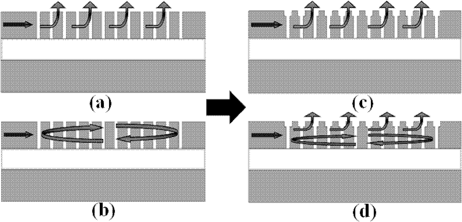
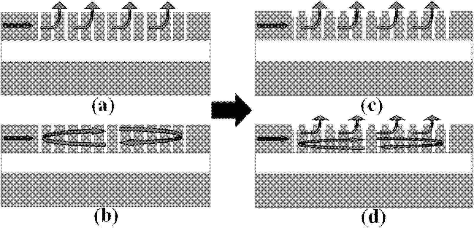
[0017] The purpose of the present invention is to provide a design method for a novel polarization-independent grating coupler with simple structure and easy production. The specific implementation is divided into the following five steps:

[0018] 1. Obtain the period T of the TM mode according to the grating coupling Bragg condition TM ;

[0019] Usually based on the grating Bragg conditions for the TE and TM mode grating couplers of the same wavelength, the grating period will be very different due to the large effective refractive index difference between the two. Here we consider that the TM mode still follows the grating Bragg condition for coupling, then the grating period T TM Should be λ / n eff TM (λ is the coupling wavelength, n eff TM Is the effective refractive index of the TM mode). For the Slot effect of the TM mode, the grooves of the TM grating adopt a vertical Slot groove structure to derive energy to achieve high-efficiency coupling.

[0020] 2. Obtain the period ...


PUM


Abstract

The invention provides a method for designing a T-shaped groove grating structure. An output coupler is realized by adopting different coupling principles for two modes so as to realize efficient coupling output by adopting the same structure for a TE mode and a TM mode simultaneously. The coupling efficiencies of the TE mode and the TM mode within a wavelength range of 1,480 to 1,580nm are both above 50 percent; and the coupling efficiencies of the two modes reach 58 percent when the wavelength is 1,550nm. The polarization dependent loss (PDL) of the coupler within a wavelength range of 1,510 to 1,580nm is less than 0.05dB and the PDL of the coupler is only 3.6*10<-3>dB when the wavelength is 1,550nm. The designed grating coupler realizes a coupling output function with high coupling efficiency, low polarization dependent loss and high bandwidth, has the advantages of simple structure, convenient manufacturing and small volume, is compatible with a standard CMOS process, and can provide technical support for the design and manufacturing of a polarization-independent device.

Description

Technical field [0001] The invention relates to the field of optical coupling, in particular to an integrated grating coupler, which has polarization-independent characteristics. Background technique [0002] Integrated silicon-based optical systems, due to their small device size and good compatibility with traditional integrated circuit CMOS processes, have become a hot spot in current research. Many micro-nano devices have been integrated on silicon, such as lasers, modulators, filters, couplers, buffers, and so on. The grating is used to realize the function of the coupler and has the advantages of small coupling area and high coupling efficiency, so it is widely used in planar optical systems. [0003] However, the grating is the same as other optical micro-nano devices. Due to the small size, the effective refractive index of the device for TE and TM modes is greatly different, which leads to the polarization-related problems of the device. The phenomenon of light-induced b...

Claims


Application Information

Patent Timeline
IPC IPC(8): G02B6/34G02B5/18
Inventor 汪毅邵士茜
Owner HUAZHONG UNIV OF SCI & TECH
Learn More